| View previous topic :: View next topic |
| Author |
Message |
Doodoob
Joined: 06 Jul 2011
Posts: 98
Location: Spokane, WA
|
 Posted: Tue Sep 03, 2013 8:13 am Post subject: Posted: Tue Sep 03, 2013 8:13 am Post subject: |
 |
|
| Great job! I love to look at all the updates. |
|
| Back to top |
|
 |
Baxsie
Joined: 12 Apr 2012
Posts: 253
|
| Posted: Sun Sep 15, 2013 4:23 pm Post subject: Making modern fan shroud work with Fuel Injection (right) |
|
|
| dukebradbury wrote: | Baxsie,
You are killing it!!! Great job. Fun thread to read and watch your progress. Keep up the good work and keep the pics coming!! |
| Doodoob wrote: | | Great job! I love to look at all the updates. |
Thanks for the encouraging words. Seems insurmountable somedays.
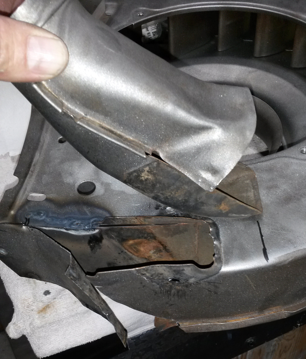
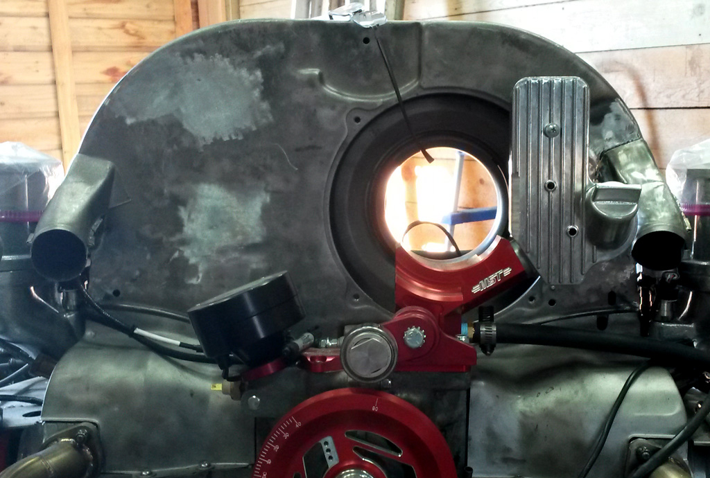
I took on clearancing the right side of the fan shroud to make room for the fuel injectors and fuel rail.
Opening it up, as before:
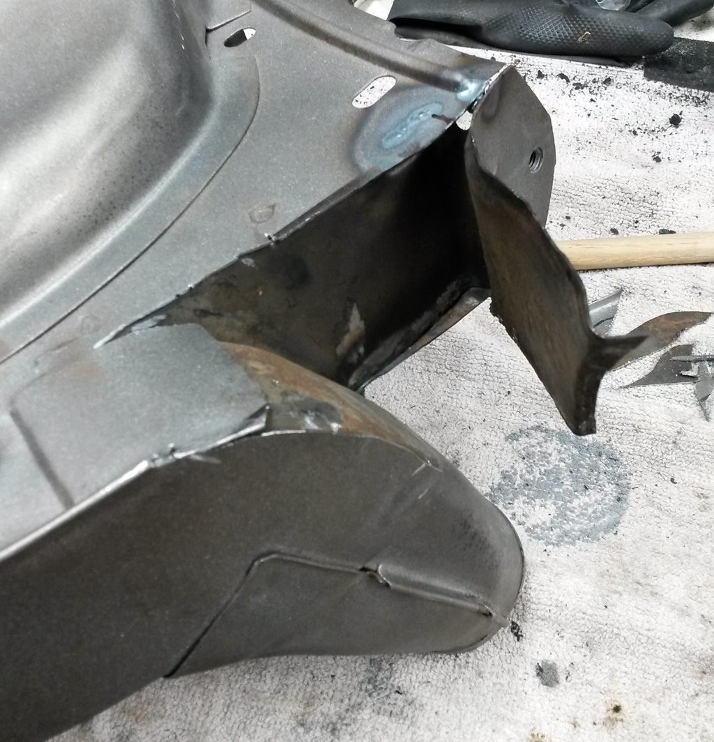
Since the right side cylinders are farther back, we needed to relocate the heater air outlet higher:
Here is a shot from the front, showing there is now clearance:
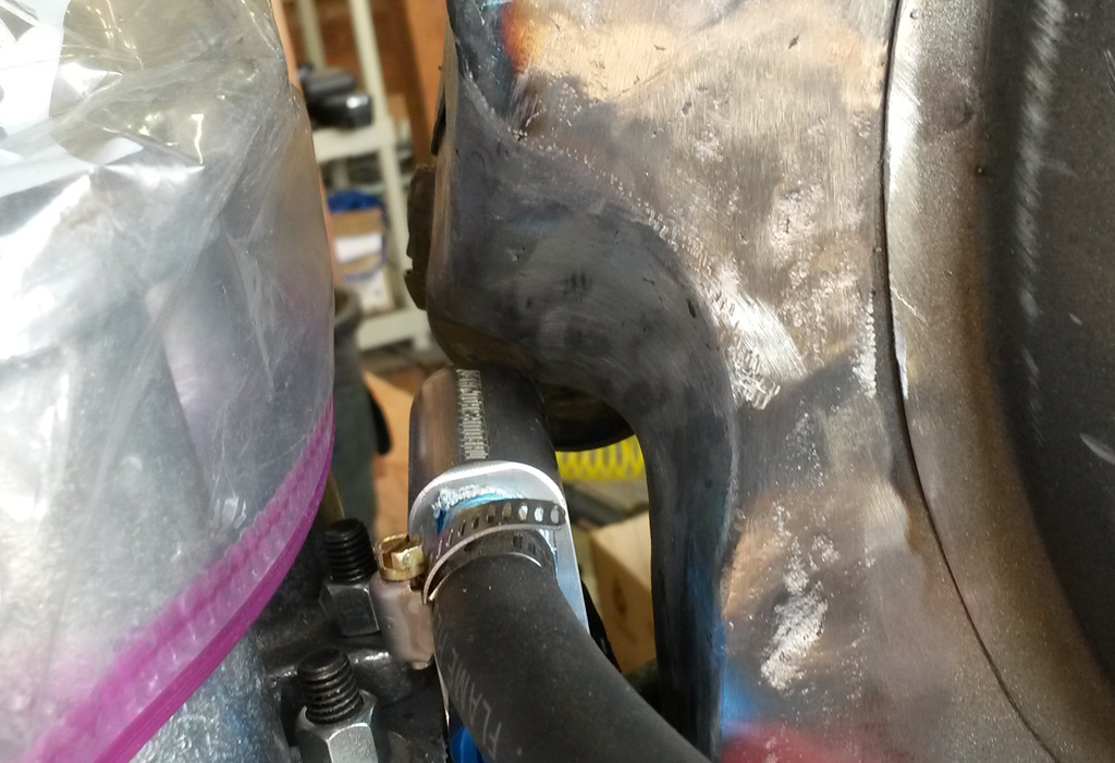
And a shot from the rear:
If you look really close, you can see that the right side outlet is a bit higher, but there is so much noise in the engine compartment that I do not think it is very noticeable. Also removed the coil mount holes and spark plug keeper holes:
Now for another quick bead blast, some DTM primer, some filler primer and sanding . . .
Last edited by Baxsie on Fri Aug 08, 2014 11:55 am; edited 1 time in total |
|
| Back to top |
|
|
Baxsie
Joined: 12 Apr 2012
Posts: 253
|
| Posted: Mon Oct 07, 2013 8:48 pm Post subject: |
|
|
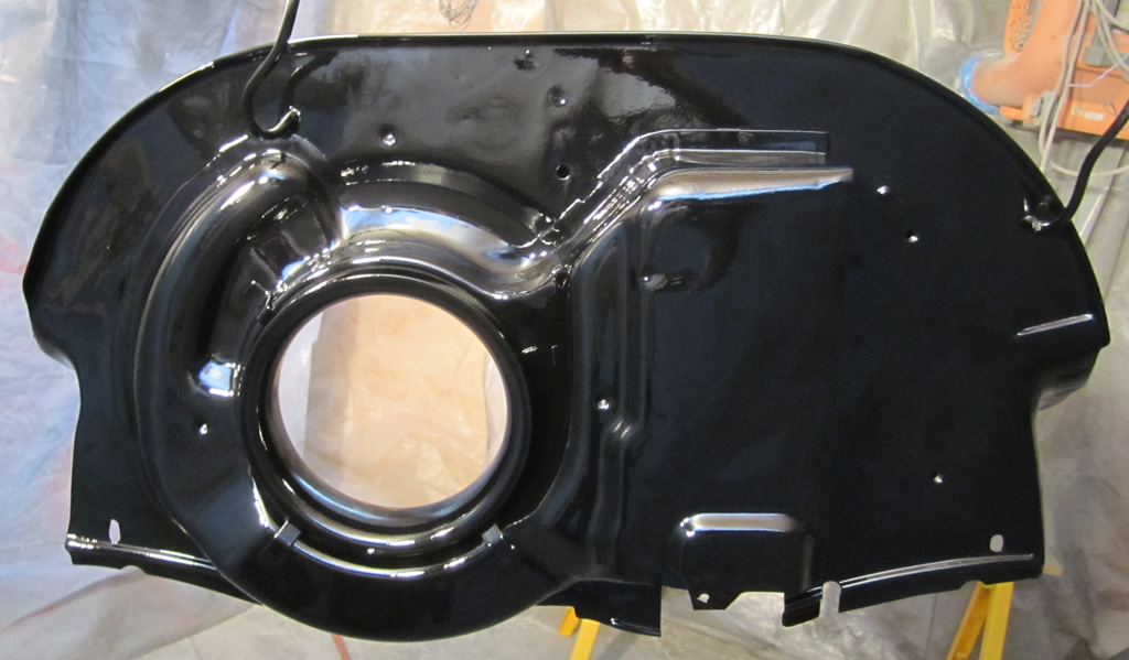
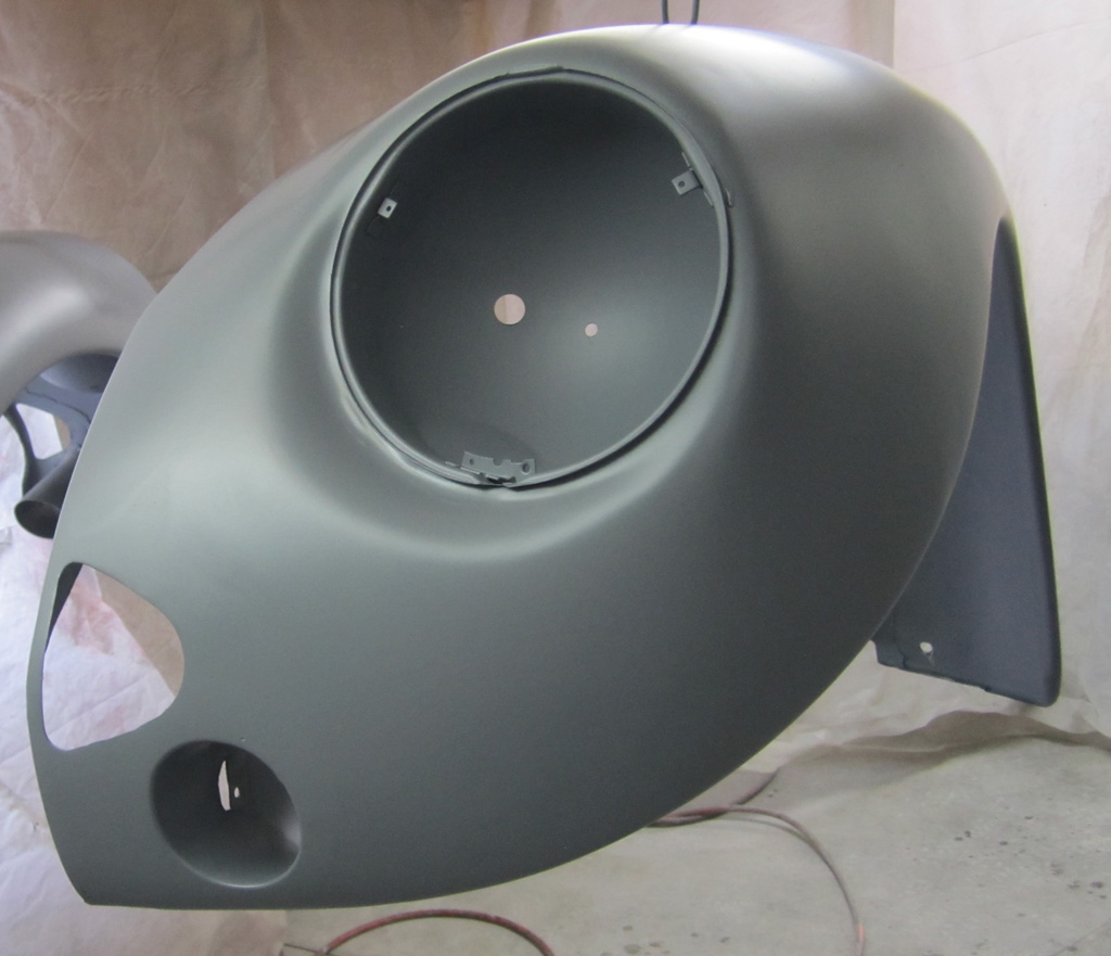
Things have been going a bit slow. The boy is super busy with school, cross country and pep band. Meanwhile I have been keeping myself occupied by puttering around on the fan shroud injector clearance project. I used some primer and a bit of body filler (sorry), and finally got it prepped to where I tried painting it.
Eventually it will end up getting another sanding/scuffing and then get shot with the body color. For now I shot it with some of the gloss black we had for chassis parts.
My biggest challenge was getting the large flat area actually flat. There was the normal warping from taking out the spark plug wire guide holes and the coil mounting holes. It actually looks pretty good in person:
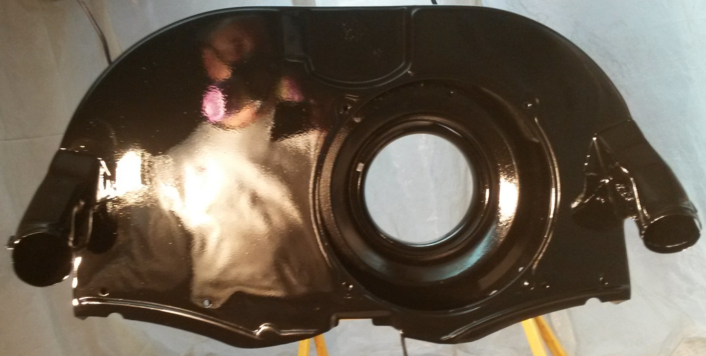
Definitely not perfect, but I did learn a bit about prepping and painting:
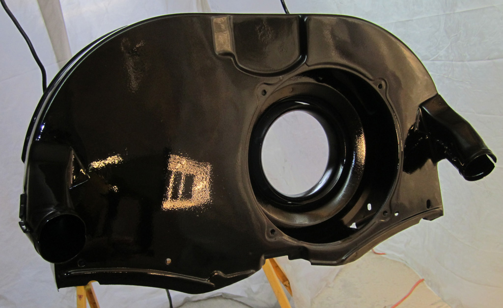
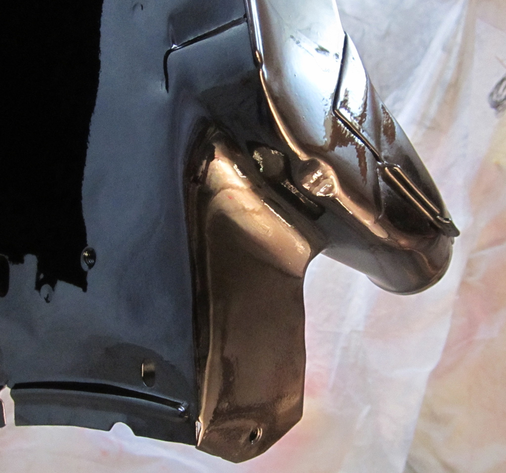
I also worked on smoothing out the tooling ridges around the corners and on the top edge:
I spent less time on the back side, though there was an emissions tube attachment removed:
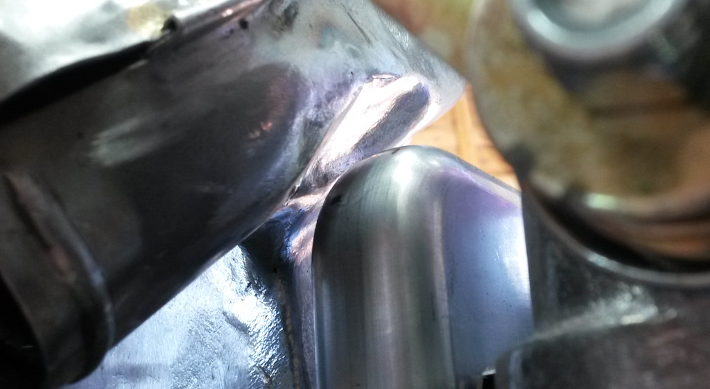
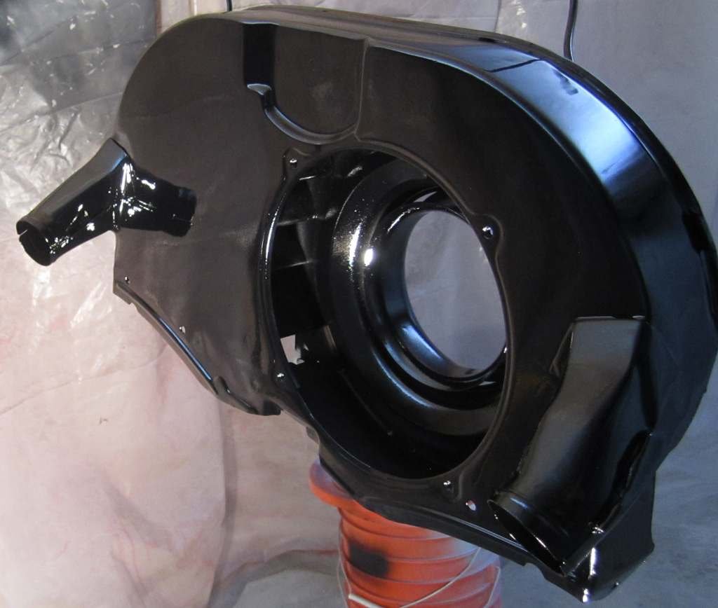
Detail of the driver side injector clearance work:
Detail of the passenger side injector clearance work:
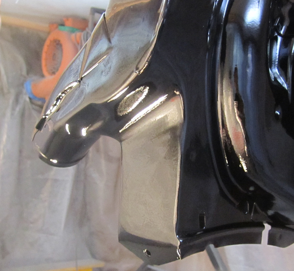
Overall, I think it is a pretty good solution. All the injector clearance you would get with a 36hp style shroud and all the late-model advanced airflow engineering.
Last edited by Baxsie on Fri Aug 08, 2014 11:55 am; edited 1 time in total |
|
| Back to top |
|
|
Baxsie
Joined: 12 Apr 2012
Posts: 253
|
| Posted: Sat Oct 19, 2013 8:55 am Post subject: |
|
|
Over the last couple of weeks, we have been working on installing the seats. We placed the original seat back in the car, to measure where the new seat should be positioned. We then placed the new seat on blocks to verify that things felt right. Once we had the height and fore-aft locations set, we could start fabricating.
My guess is that most people will think this is a bit on the over-done side. Well, you know: "If it's worth doing, it's worth overdoing." Seriously though, we wanted to do our best to make sure the safety and support that the new Recaro Speed S seats offered would stay anchored to the chassis in the case of a collision. Being strapped in a seat won't help if the seat is slamming around inside the car.
Since the bottom portion of the new seats are thinner than the stock seats, the mounting sits quite high. We decided to anchor the inboard side of the seat directly to the tunnel, using formed 2"x1/8" flat stock to make a reinforcement:
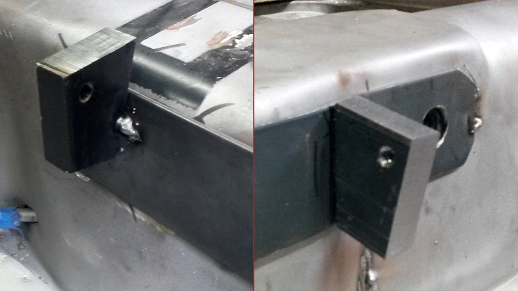
The mounts are made of some thick steel stock, shaped then drilled and tapped to mate with the hardware supplied with the seat:
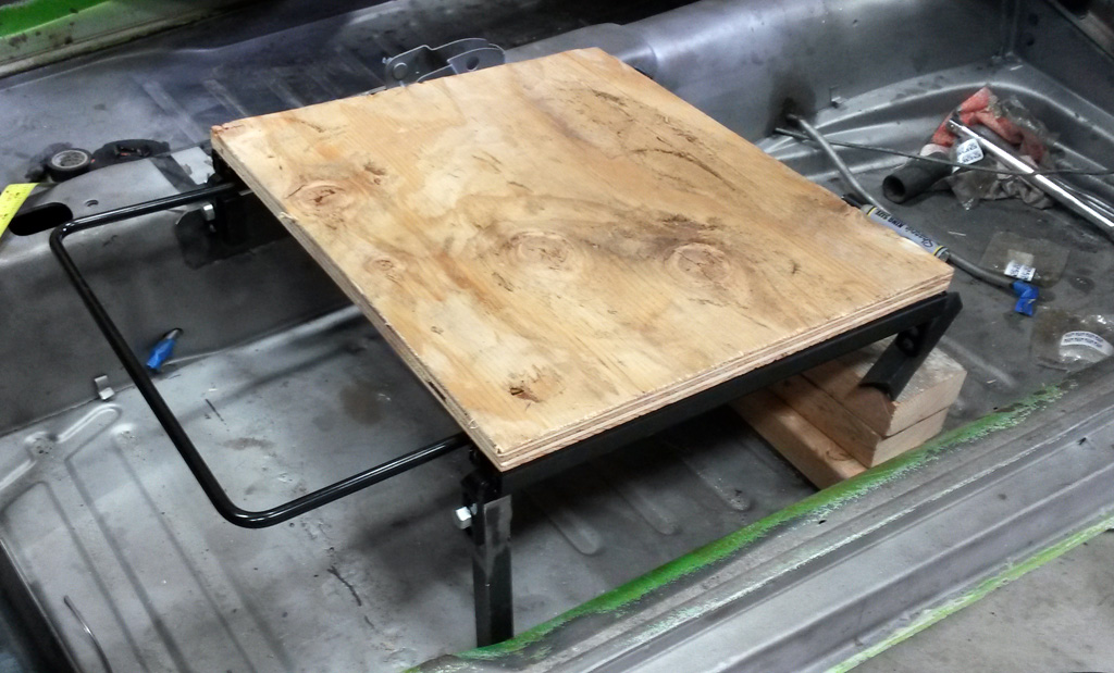
We carefully mounted the seat's sliding rails to a piece of plywood, so we could check for spacing and level:
Here is the construction of the outboard posts. We started with a fairly heavy angle, then welded a cube of the thick steel stock to the end. We then cleaned it up, drilled and tapped it:
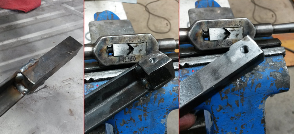
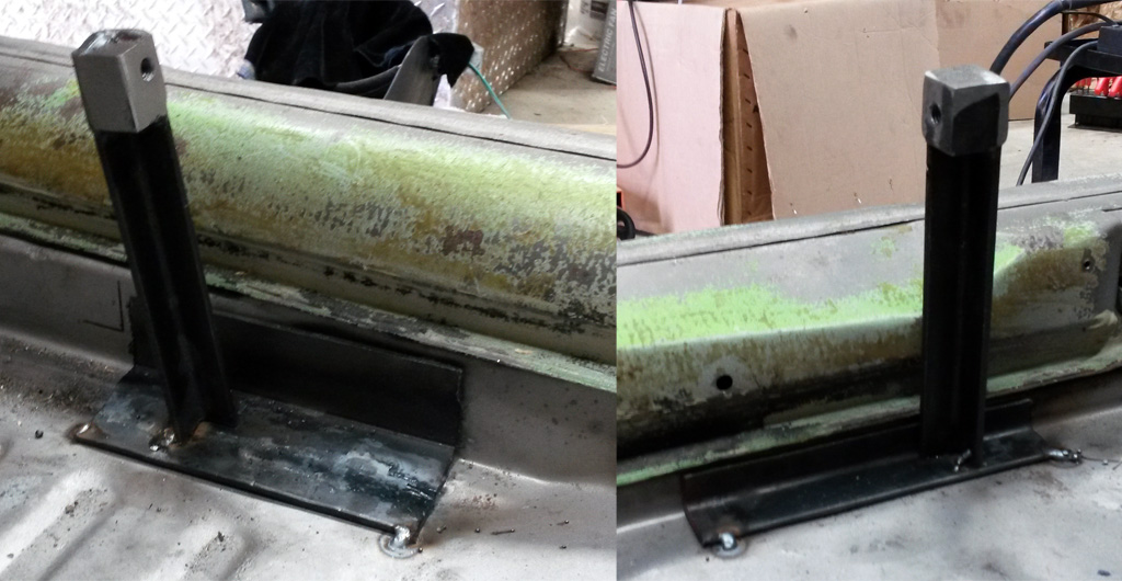
The outboard posts are welded to angles, the angles cut or formed to match the pan contours:
Once the posts were installed, we carefully measured square and cross bracing made of 1/2" square steel tube. This was all test-fit against the plywood-mounted rails to be sure things moved smoothly:
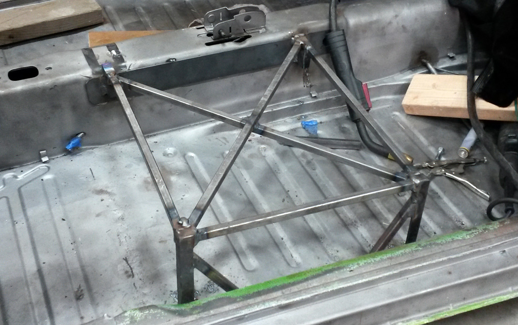
A shot of the bracing from another angle:
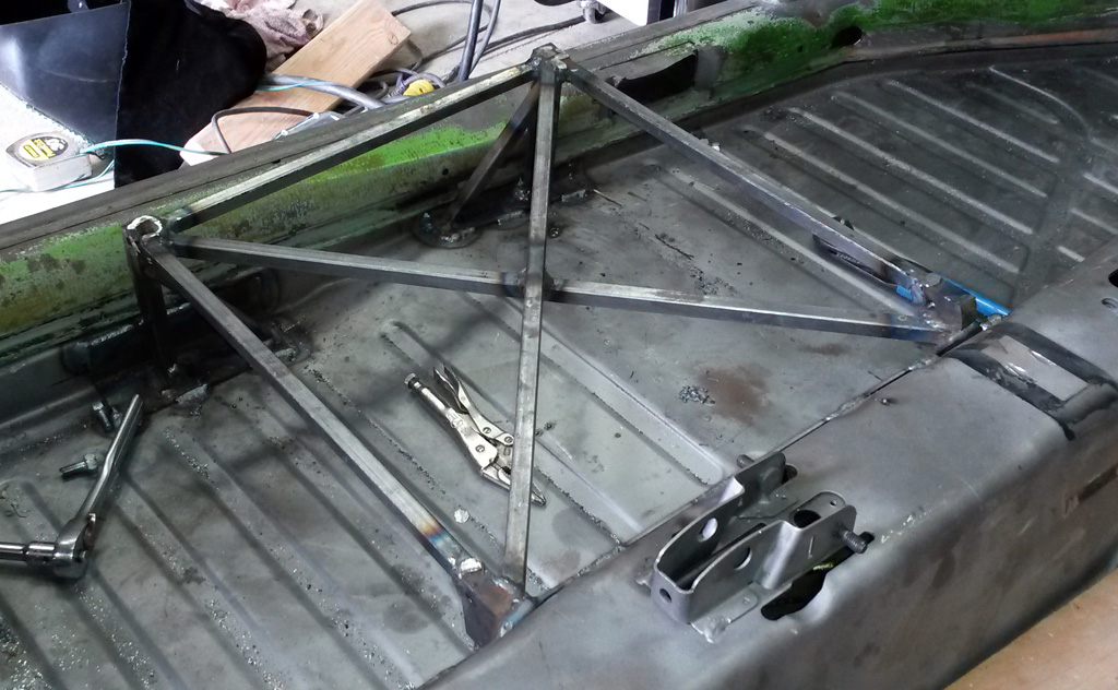
We are getting ready to start on the passenger side:
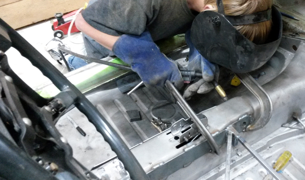
Here is a video of the action:
http://www.youtube.com/watch?v=DDvRcOkkLOk
And the result:
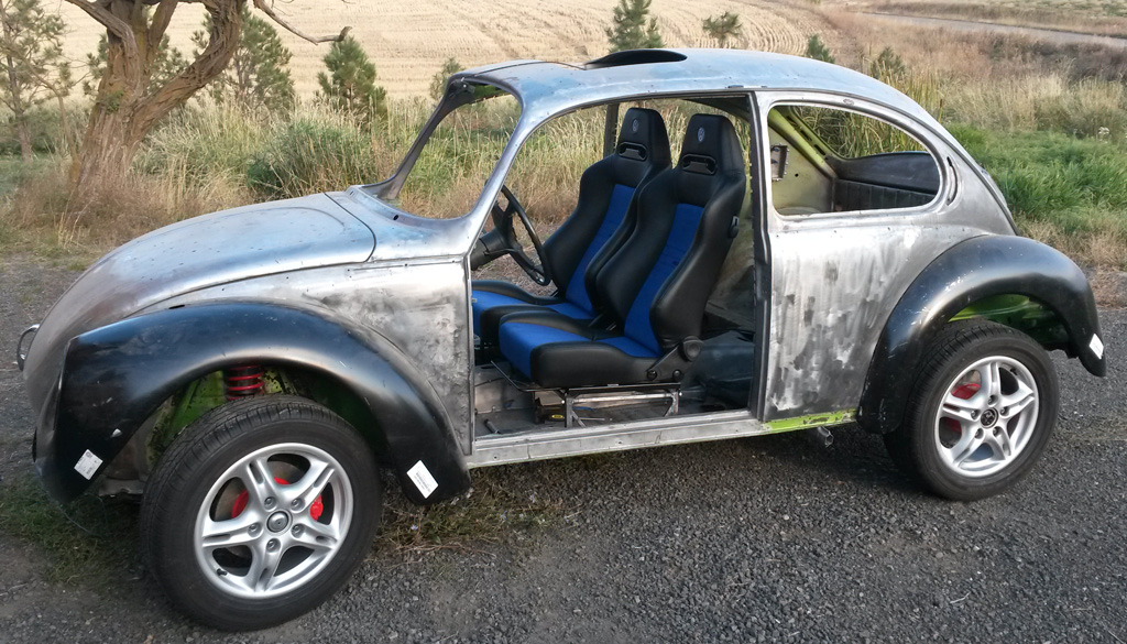
Here is a picture of both seats installed, in the middle of their travel:
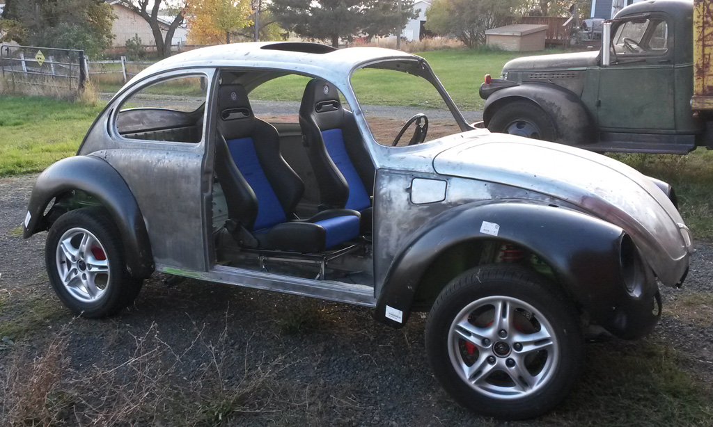
Here is the passenger seat all the way back, driver all the way forward:
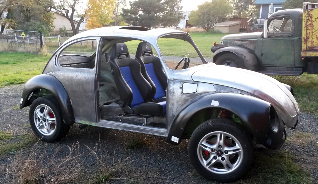
Both seats all the way forward:
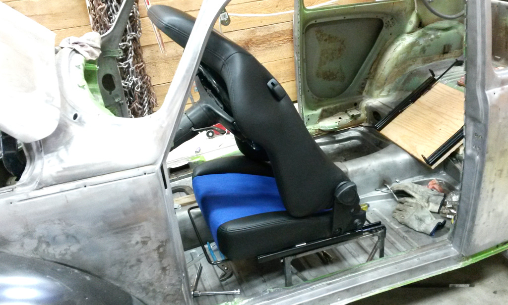
The seats fold forward for easy rear seat access:
Last edited by Baxsie on Fri Aug 08, 2014 11:54 am; edited 1 time in total |
|
| Back to top |
|
|
Baxsie
Joined: 12 Apr 2012
Posts: 253
|
| Posted: Sat Nov 02, 2013 11:00 am Post subject: Vintage Hurst Shifter Repair |
|
|
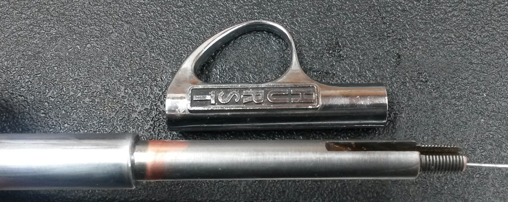
One of the background projects has been to repair/rebuild a Hurst Shifter that we picked up at the local salvage yard, out of a 1973 Super. It looked pretty rough, and was missing a knob, but who could say "no" to Hurst?
The most obvious problem was that the upper plastic plate was cracked. We drilled out the rivets and assessed the damage. It appears that other (later?) shifters had a thicker/stronger top plate (photo from Chadwick James Moore's Samba Ad):
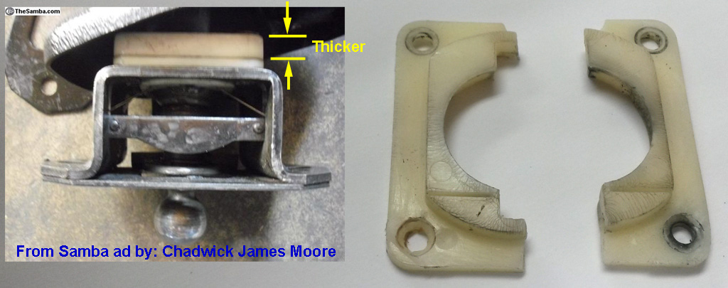
We figured that just gluing would be futile, so we used some control cable as rebar to strengthen it. The vise grip pliers are holding a good stiff tension on the wire:
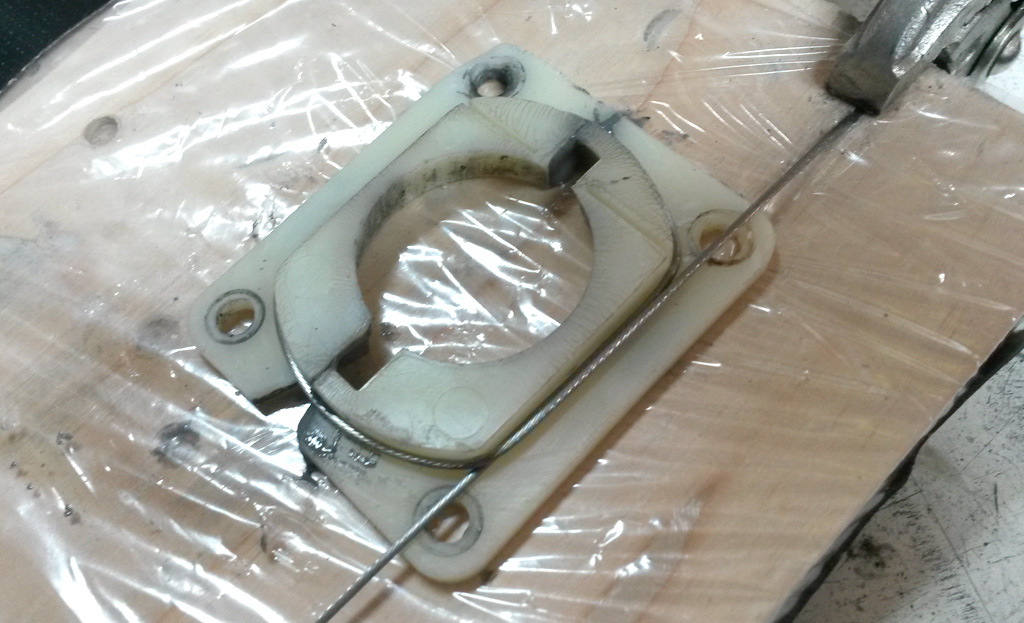
Then slathered on the JB-Weld Epoxy. On each of the four corner mounting holes, we embedded and external tooth lock washer in the epoxy, so that tightening the mounting bolts would not crush the plastic and blow out the corner holes. The washer in the upper right of this image is visible, the others are submerged in epoxy:
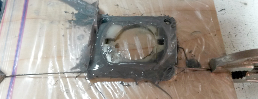
Here is what it looked like after the epoxy has cured:
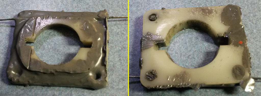
We then trimmed the reinforcing wire, and cleaned it up on the belt sander and used a file to flatten the corners. Here you can see the external tooth lock washers embedded in the epoxy:
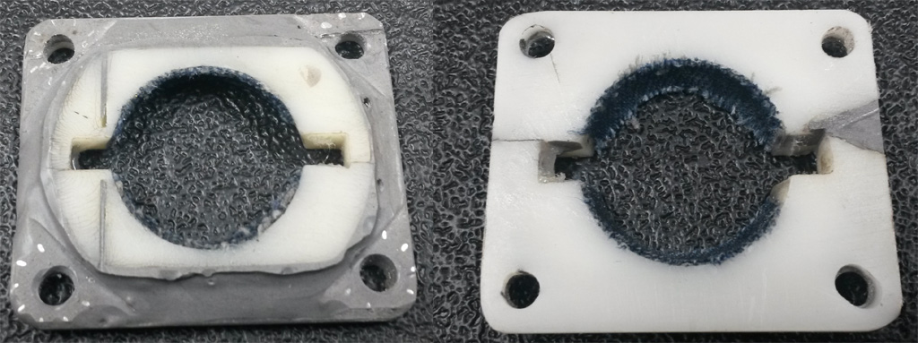
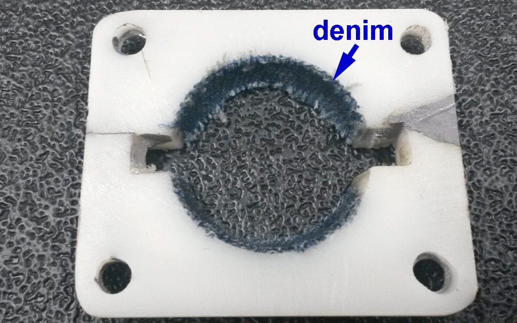
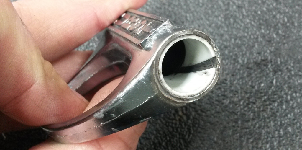
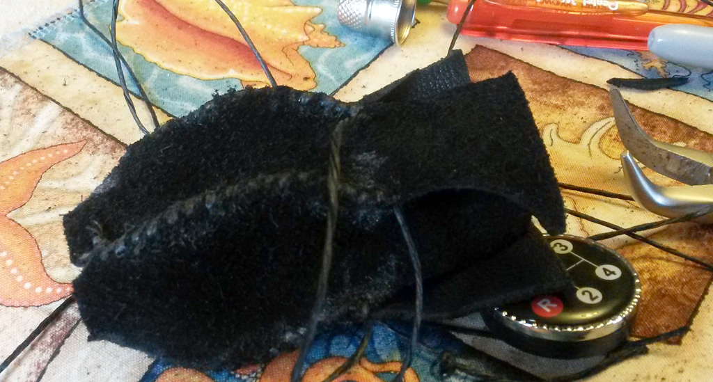
The ball was still loose when sandwiched by the two plastic plates. Initially we thought that sanding some material off the plates' mating surfaces would tighten it up OK. After looking again, the amount of material we would have to remove was way too much. Instead we cleaned the plate thoroughly and used superglue to bond a piece of denim cloth to the upper plate's socket, then trimmed it with a razor:
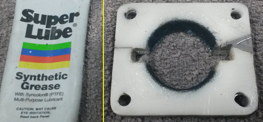
For lubrication we used some synthetic grease we had on hand. We were worried about a petroleum lube attacking the plastic over time:
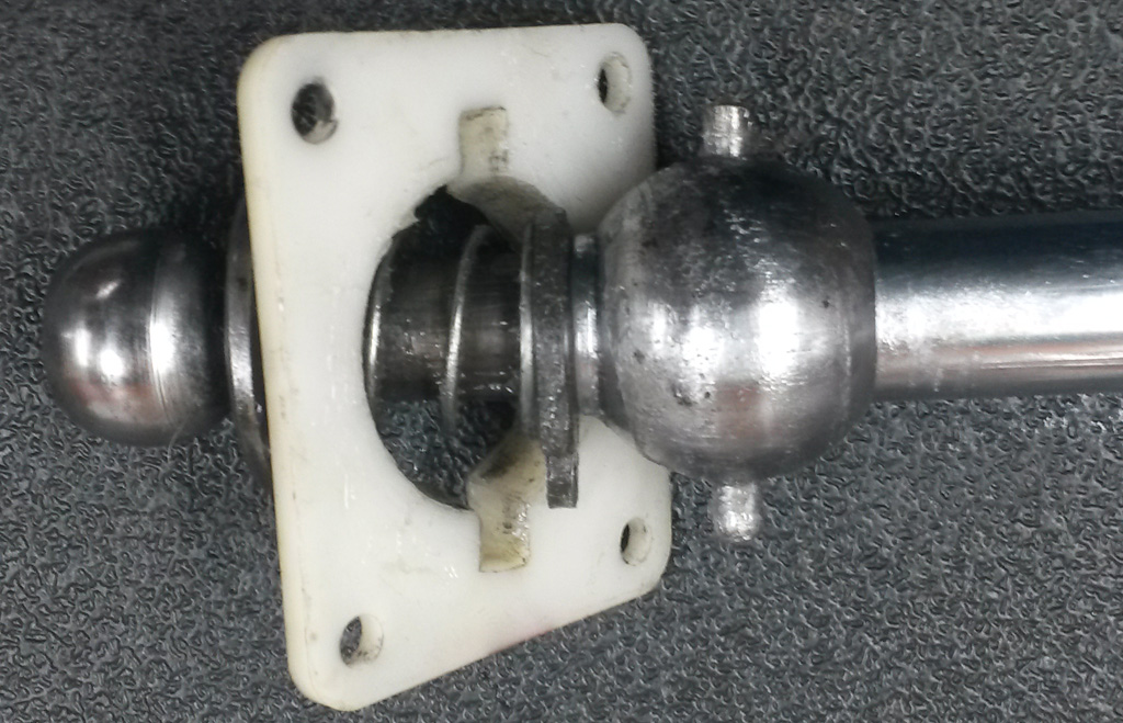
The main ball had some pretty nasty rust. We worked through: wire brush, 600, 1500, then polishing compound. The lower ball was in much better shape, requiring only a bit of polishing. We thought the assembly method of these three pieces was poor. There were two short roll-pins, one each pressed through the ball, through the wall of the main shaft, and then nudging into a small recess on the shaft of the lower ball. Pretty much asking for slop. We drilled through the shaft of the lower ball, then pressed a single solid pin all the way through. The pin was cut from the end of a punch, so it is nice, hard, strong material. This assembly is rock solid now:
We cleaned and polished the shaft where the trigger slides:
There are some spiral cut plastic bearings inside the trigger. We did not like the way those bushings could move around freely inside the trigger. They tended to bunch up at one end. After roughing the outer surface of the bushing and cleaning the inner bore of the trigger, we used epoxy to fix them in position, one at each end of the trigger. At final assembly this slide was lubed with the synthetic grease:
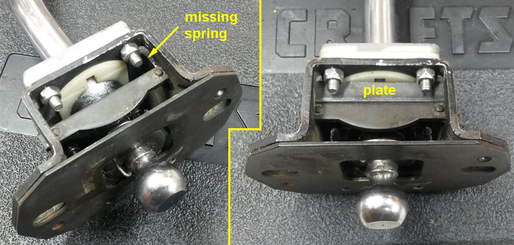
From pictures in the Samba classifieds, there should be a spring that moves this crescent shaped bar down, but also allows it to ride up. Our spring was missing, of course. As far as I can tell, having the spring allows you to pull the reverse lockout trigger when you are in the 3-4 side of the H, but does not allow you to move into the 3-4 side of the H if the trigger is pulled. We ended up fixing this slide in the down position with a plate. If you are in the 3-4 side of the H you simply cannot pull the trigger, and if the trigger is pulled, you cannot move into the 3-4 side of the H. If real-life operation proves that the spring is needed, we can easily remove the plate and source or fabricate a suitable spring. There is also a separate spring that makes the stick "idle" to the 3-4 side of the H. Of course this was missing, but I was able to find a suitable substitute at my local hardware store:
Here is a video that shows the lockout operation of this shifter:
http://www.youtube.com/watch?v=eSItBOX8ZfU
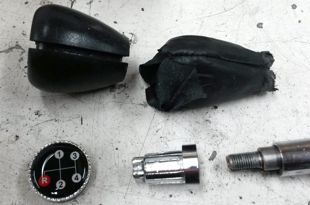
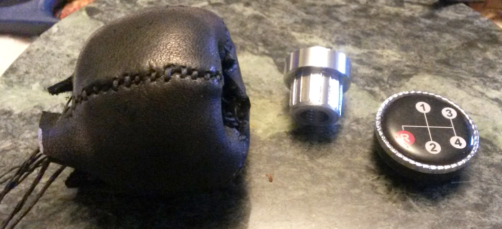
Since our shifter did not have a knob, and my son wanted one with a pattern on it, we got this EMPI knob:
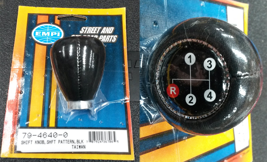
The original plan was just to screw it on and be done. But of course the threads on the Hurst shifter are american 3/8-24, and the EMPI knob only had metric sizes in it. We secured a 3/8-24 coupling nut and used the belt sander and a drill to reduce its diameter and make the outside round:
The idea at this point is to drill out the EMPI knob's insert to accept the 3/8-24 insert and glue it in place. That all went to heck. Even though we left the EMPI knob in the vacuum pack plastic, and wrapped it in a cloth, in the vise, by the time the drilling was done the knob had slipped in the package, and this had messed up the vinyl covering on the knob. The whole thing ended up coming apart:
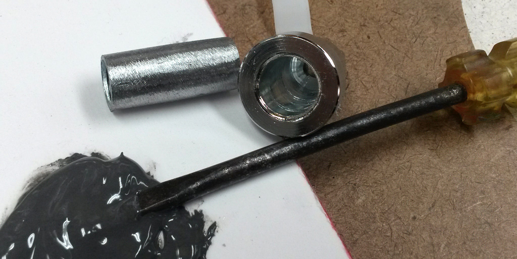
Sigh. We went ahead and glued the 3/8-24 insert into the now-drilled knob insert, using epoxy and a light press of the vise:
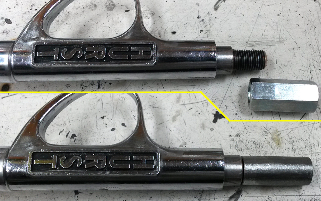
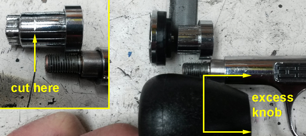
After test-fitting the knob (without a cover) we decided the knob was too tall anyway. It was a bit of a stretch to get your finger down to the trigger. We cut some off the threaded insert, then made a stack-up to see how much the knob could be shortened:
A quick trip to the farm-boy lathe:
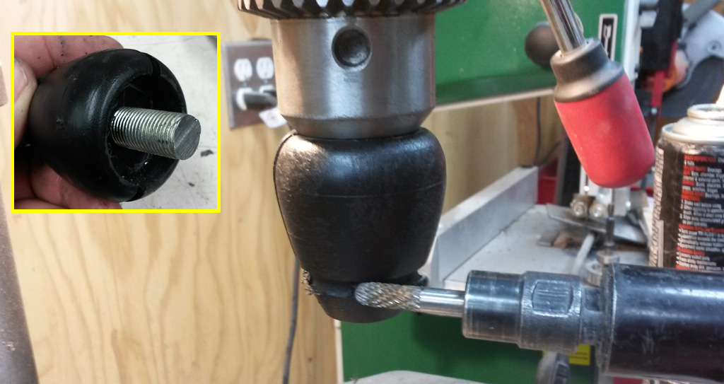
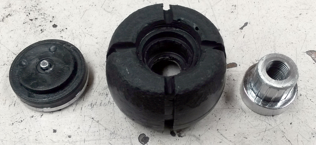
Now the knob is quite a bit shorter (closer to the Hurst ball's shape) and is ready to cover. Note that there are four groves in the knob that the seams will recess into:
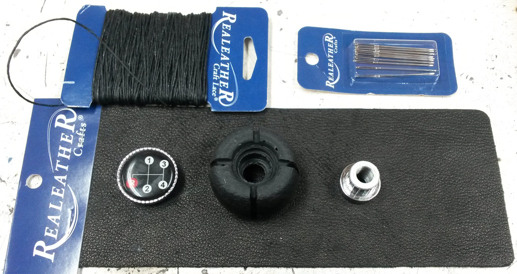
The local craft store had some leather working supplies, surprisingly cheap:
Here the leather is on the knob inside-out, as I am trying to mark the shape that each of the quadrants needs to be. It took a couple of iterations, then a final trim of all four pieces stacked to make sure they are the same size and shape:
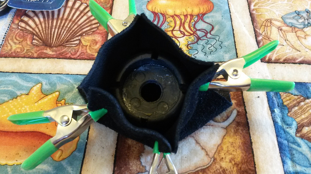
Once the shape is close, I stitched the leather inside-out tightly over the knob:
Right-side out again, and pull it over the knob, lining the seams up with the grooves in the knob. Now the inserts are ready to be glued and pressed back in:
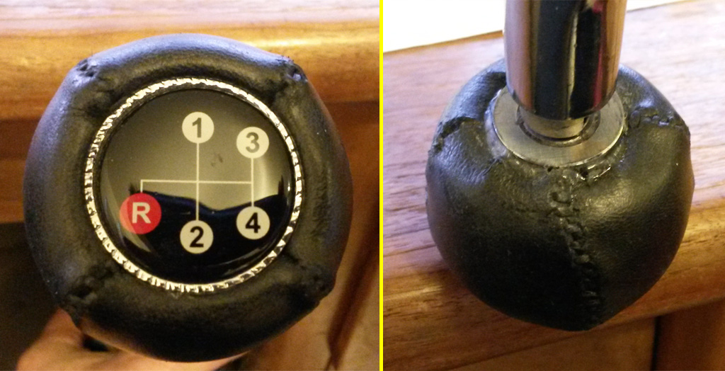
Considering that I am a rank amateur leather-worker, I do not think the knob came out too horribly:
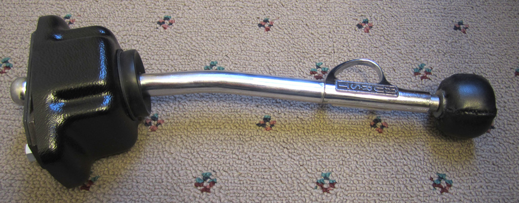
At this point, the whole project came off the tracks. We installed the shifter in the chassis, sat in the seat and tried it out. We immediately found out why there is a short-straight version of this shifter, in contrast to this long-angled version. Maybe the long-angled one is made for a sand rail or something? In any case, pulling back to 2nd or 4th plants your elbow firmly on the seat back. Completely unusable. Frustrated, we decided to straighten and shorten it. If we messed it up we would just buy the correct version out of the classifieds and junk this one.
So we disassembled everything, heated a PVC pipe and slid it over the shaft to protect the finish. We put it in the press and straightened it as far as we could take it in one go. We then cut ~1 inch off the lower end of the shaft and re-drilled for the pin, and re-assembled.
With these modifications, you can shift it without bumping your elbow on the seat back, yet it still has a slight backwards rake.
We purchased a new rubber bellows/seal thing (a repair part for the EMPI knock-off). The vacuformed base was not in bad shape, but it had some odd light-colored spots on it. We gave it a light bead blasting, then shot it with some satin black Krylon "Fusion for Plastic" spray paint that is intended to bond well to plastics. Frankly it looks brand new. Hopefully it will hold up well over time:
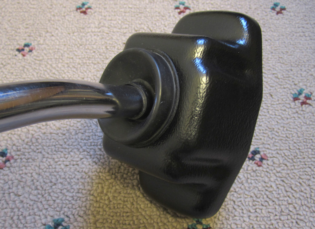
Here is an image of the overall straightened/shortened shifter:
Last edited by Baxsie on Fri Aug 08, 2014 11:54 am; edited 1 time in total |
|
| Back to top |
|
|
Baxsie
Joined: 12 Apr 2012
Posts: 253
|
| Posted: Sun Dec 22, 2013 10:42 pm Post subject: Mounting Oil Cooler and AC Condenser |
|
|
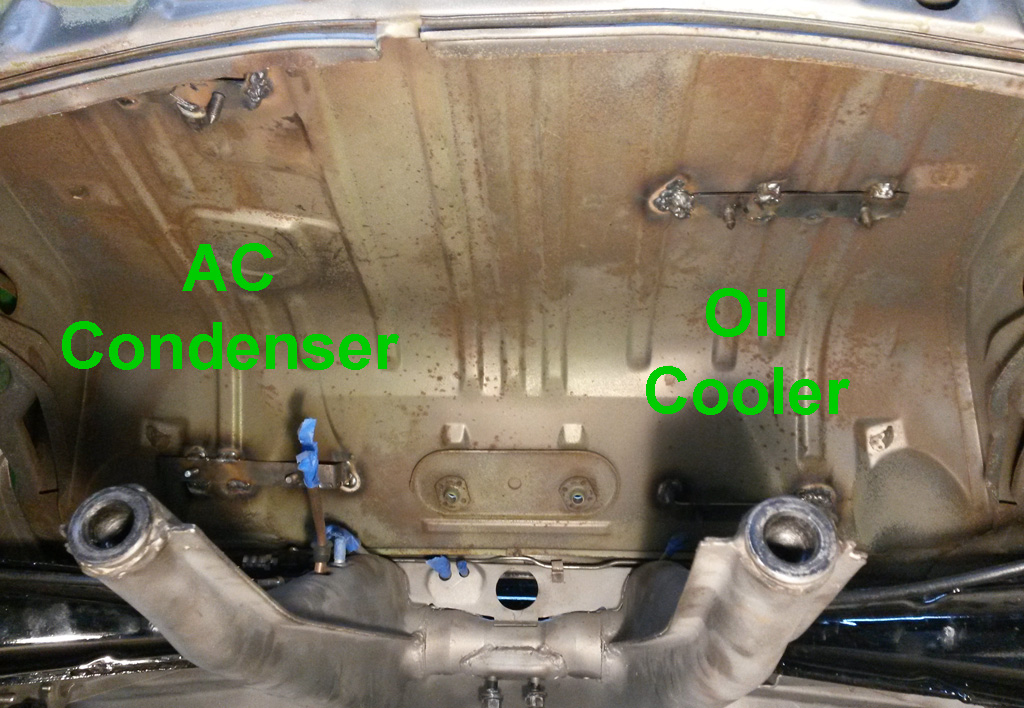
We got one to the Atomic Cool oil coolers from CB Performance. We decided to mount it and the ICE AC condenser ("helper" or "pre-condenser", the main condenser goes behind the grille way up front under the bumper) under the parcel tray, in the empty volume to each side of the transmission.
I have had some conflict whether this is the optimal location, and it probably is not. But, it is probably the best location given this particular build. Both heat exchangers have good electric fans on them, and our hope is that there will not be a "bubble" of hot air building up in this area under the car. If the car is moving, no worries . . . but if just idling on a hot day I am not sure the flow will work out. Time will tell.
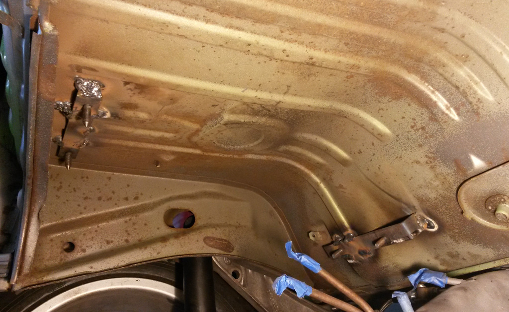
Here is a test fit of the oil cooler, with the transmission in:
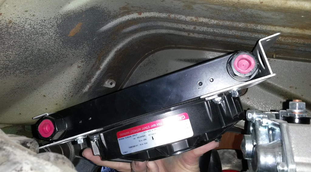
That showed us that the bracket angle needed to be adjusted:
Another test fit with the transmission is out of the way:
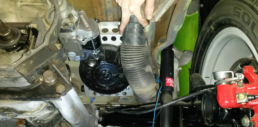
We then put the transmission back, and checked the heater tube clearance. Not great, but it should work:
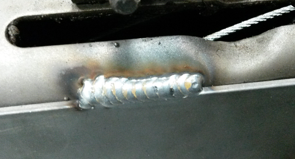
Here is where the oil cooler brackets ended up (please ignore the horrible overhead welds):
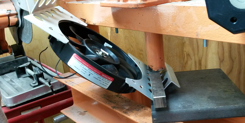
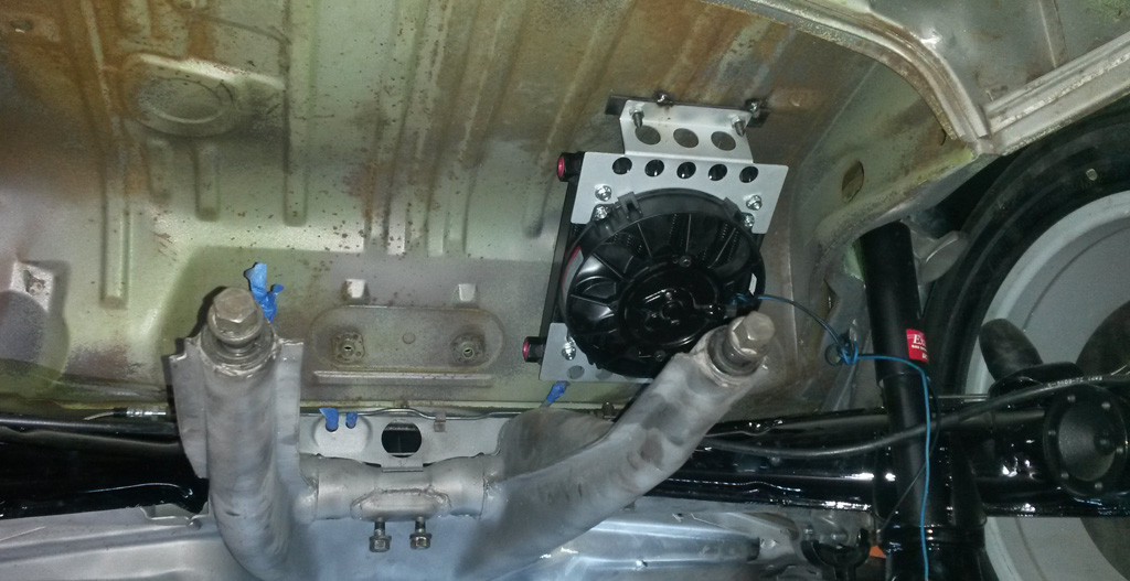
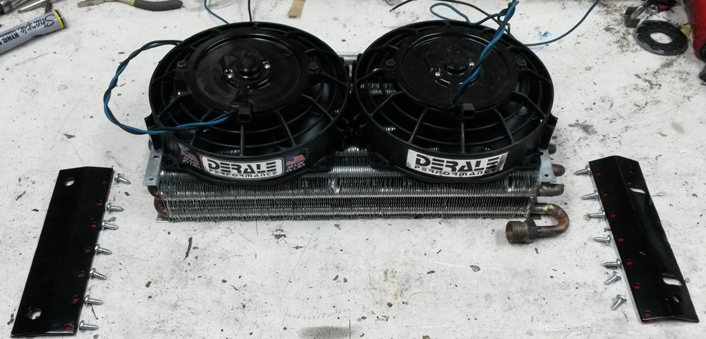
The AC condenser is a similar setup. ICE AC (apparently now out of business . . . great!) calls for mounting the AC condenser on the front of the fan shroud over the intake. So on the hottest days when you need AC the most, add some more load to the engine and then heat up the air going into the engine for good measure. No thank you. Instead we opted for two Derale 7" fans that fit pretty darn well on the condenser:
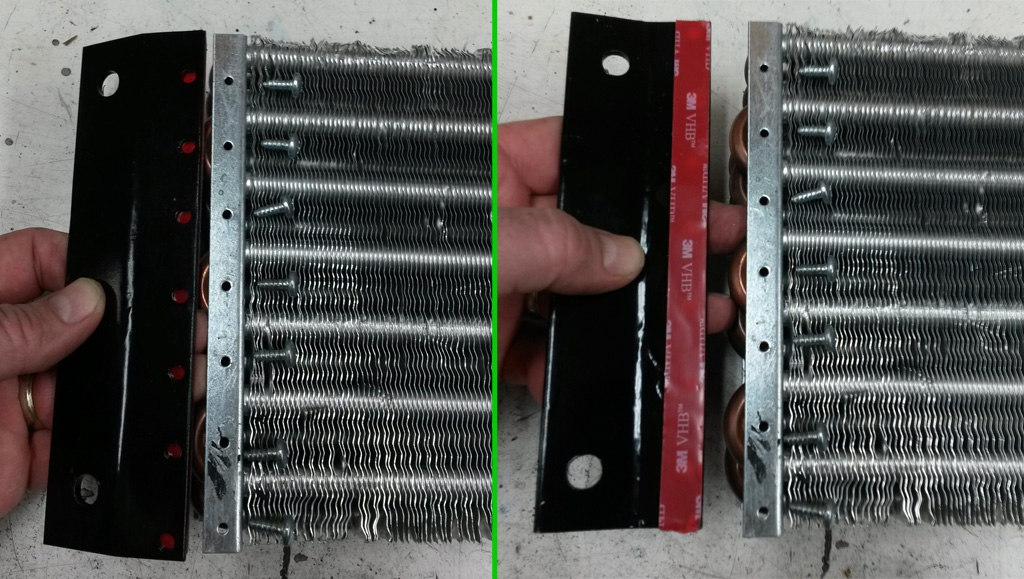
We made two angle brackets that will screw to the condenser flange (and 3M VHB mounting tape for peace of mind), these brackets will bolt to the mounting brackets that are welded to to the body:
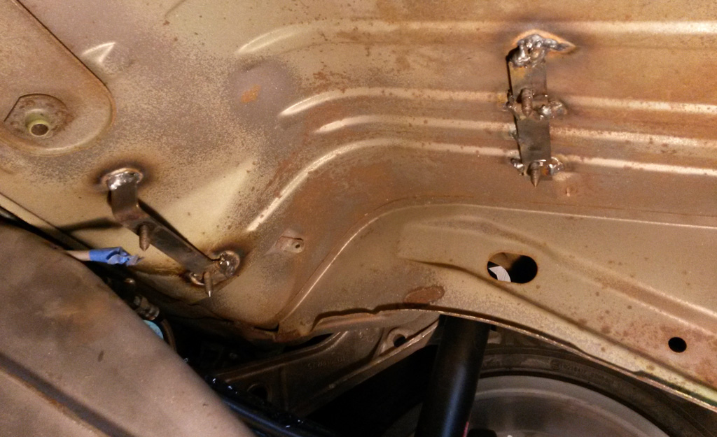
Here are the parts of the AC bracket that are welded to the body:
A parting shot of all the brackets:
Still need to work out how to plumb all that stuff up.
Last edited by Baxsie on Fri Aug 08, 2014 11:53 am; edited 1 time in total |
|
| Back to top |
|
|
Baxsie
Joined: 12 Apr 2012
Posts: 253
|
| Posted: Sun Dec 22, 2013 10:48 pm Post subject: Making the Front Fenders Wider -- "Easy" Method |
|
|
We have really been searching for a solution to the tires/wheels being too wide for the stock fenders. We thought about fiberglass, but my body guy nixed that. Well, he might have second thoughts after seeing this post 
It seems that most fender widening project involve inserting a strip of metal into the fender. Fair enough, we even bought a strip of metal the correct width. Then it occurred to us that we have the old fenders to use. So our plan was to use a strip of the old fender, and combine that with the new fender. How hard could it be . . . I've seen a guy with a MULLET doing it after all
We needed 1 1/2 inches minimum, and there was a roll of 2" masking tape . . . so we bolted up the old fender and marked off 2":
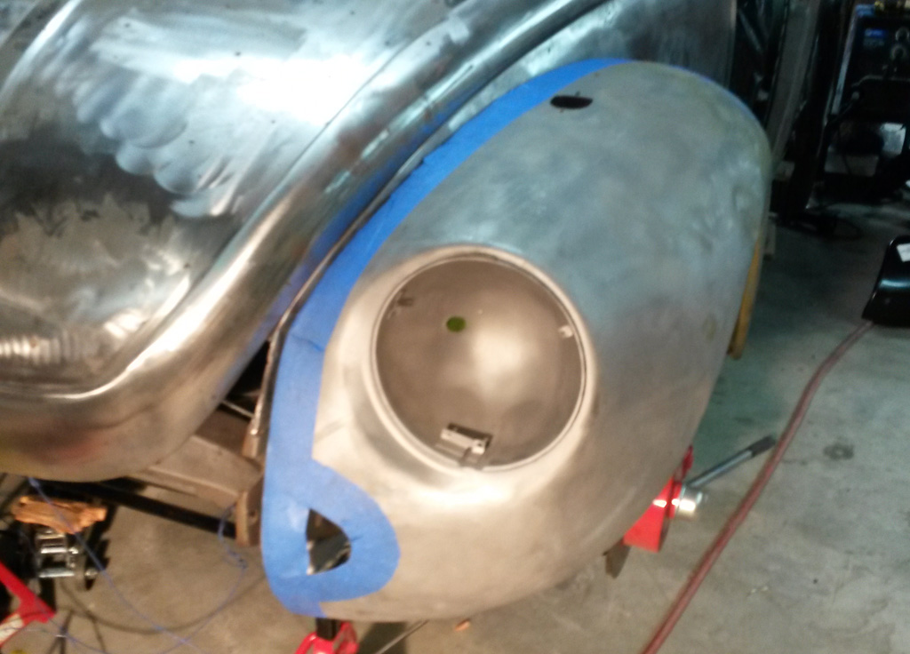
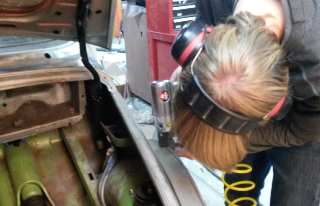
We then used a air hacksaw (affectionately known in our shop as the Noisy Cricket) to cut along the edge of the tape:
Then there were many, many test fits interspersed with head scratching:
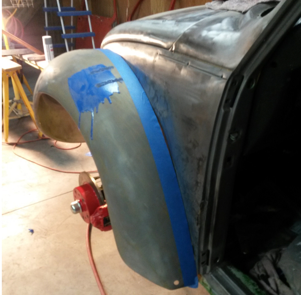
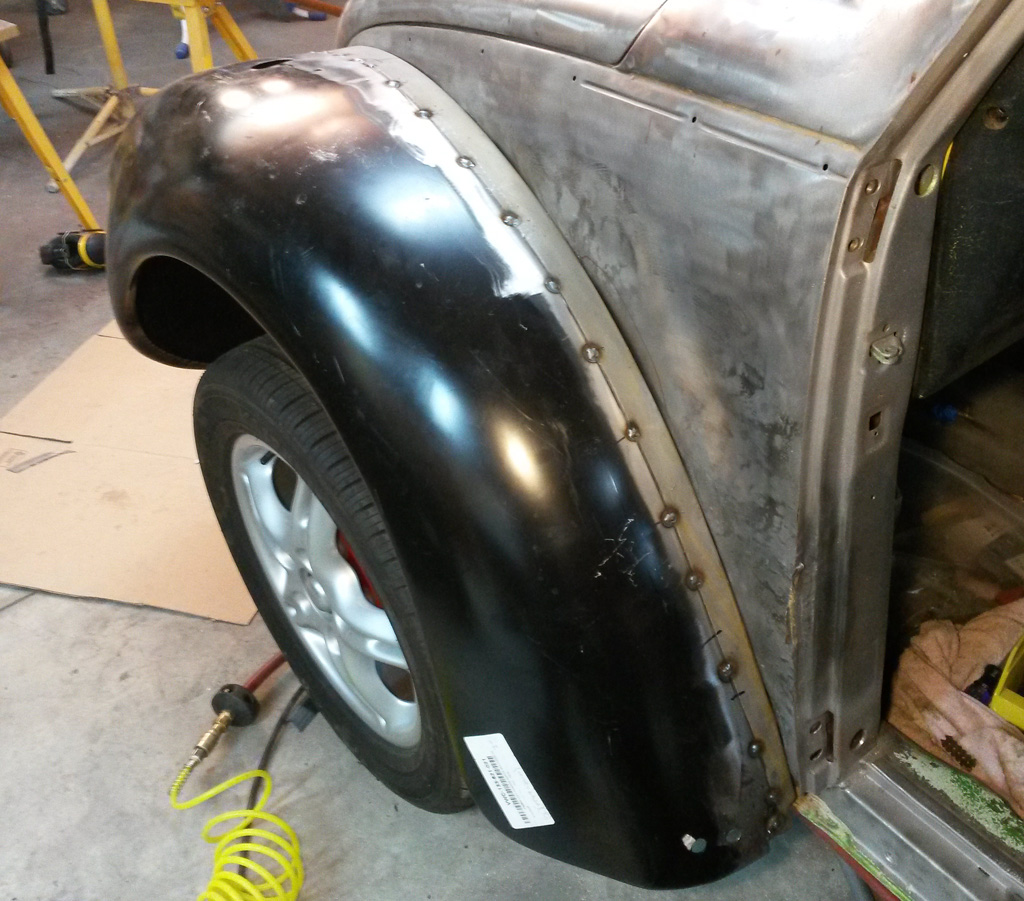
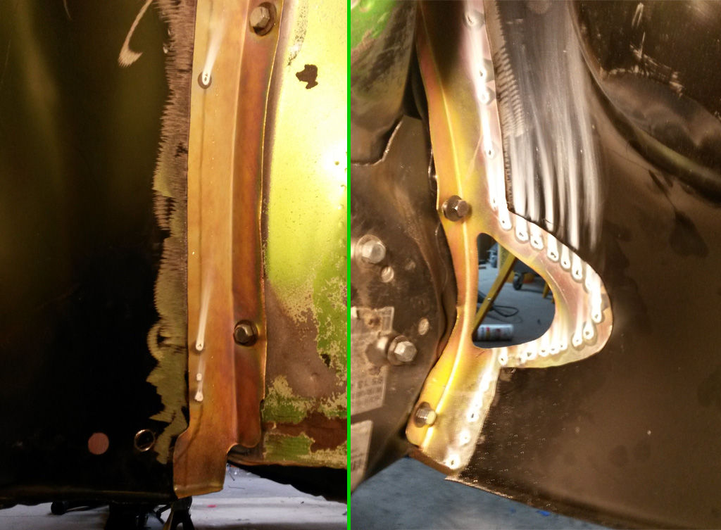
In the end the full 2" (less the ~1/4 to ~3/8: flange) is used from the lower front to the top (at the blinker). From the blinker to the running board it tapers gown to ~1". We marked a line intersecting a blinker mounting hole on the old fender, and made that intersect the same hole on the new fender:
Once we thought the test fit looked good, we put one of those step flanges on the lip of the old fender:
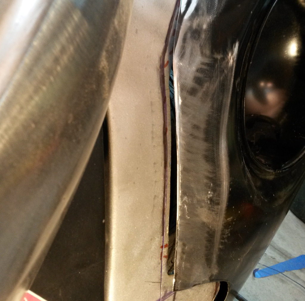
The seam lays pretty darn flat here:
We left the bumper opening in the old fender, so that the position of that did not get hosed. It is not obvious how the opening of the new fender maps to the old fender -- witness the many lines in different colors:
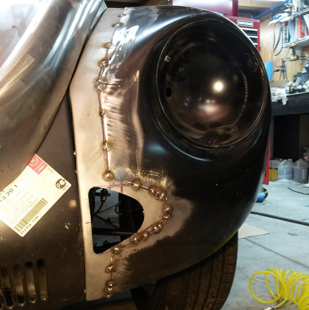
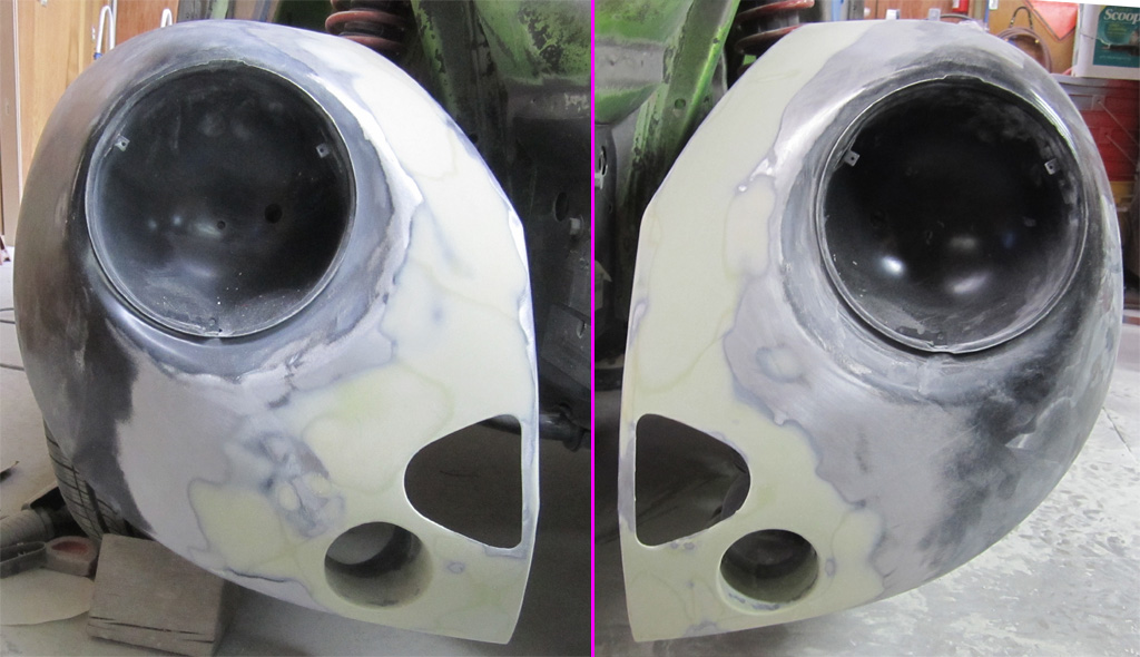
The complex curve around the headlight gives a little grumpiness:
On to the initial tack welds:
Pressing the fender into the flanged step while the boy tack welded worked pretty well and solved most of the front grumpiness:
We did end up with a pucker on the first fender. Relieving it with a slice from the Noisy Cricket calmed it down:
At this point, I took a quick cell-phone video of the first fender. It is portrait mode, sorry:
http://www.youtube.com/watch?v=_59rD9HChok
Now that we are old pros at it, of course the second fender went smoother and qiucker and came out nicer Interestingly, there was no grumpiness at the compex curve near the headlight. Taping and cutting:
Removing the bolt falnge from the new fender:
Test fit:
Flanging:
Tack Welding:
Here is anoother quick cell-phone video of the second fender. Landscape mode FTW:
http://www.youtube.com/watch?v=34MF5Oo_Tlc
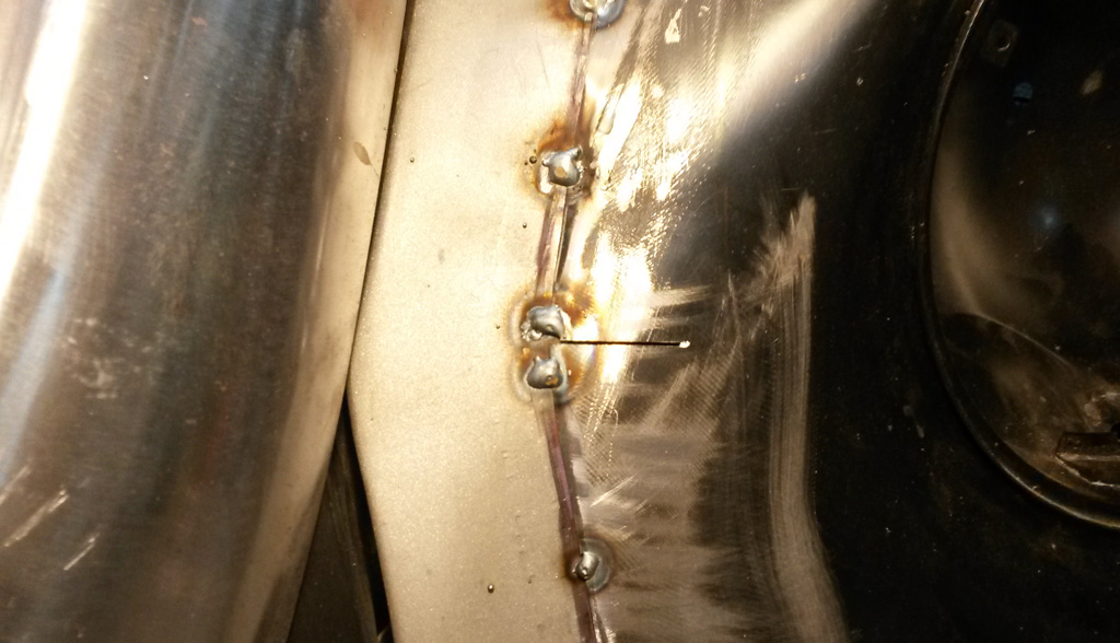
Here are a couple shots of the under-side of the second fender. We will add more welds here:
Video showing what happens on the back side of one of the welds:
http://www.youtube.com/watch?v=CRfNnALCqmc
And here is the money shot. Needs some finish work and bondo, but I think it is pretty darn good for a couple farm boys:
Last edited by Baxsie on Fri Aug 08, 2014 11:53 am; edited 2 times in total |
|
| Back to top |
|
|
Baxsie
Joined: 12 Apr 2012
Posts: 253
|
| Posted: Thu Jan 23, 2014 8:08 pm Post subject: Adding Recessed Hella Micro DE Projector Fog Lights |
|
|
We are getting a little closer on the fenders, and now it is time to tackle installing the fog lights. Here is a link to the lights we have:
http://www.amazon.com/HELLA-H13090611-Micro-Series-Halogen/dp/B00042K39C/
http://www.myhellalights.com/index.php/default/auxiliary-lamps/halogen-lamps/micro-de-series/
We also got the "PIAA 13556 H3 Style Plasma Ion Crystal Yellow" bulbs, because where I come from, fog lights should be yellow:
http://www.amazon.com/13556-Plasma-Crystal-Yellow-110-Watt/dp/B00067BV96
http://www.piaa.com/store/p/44-H3-Plasma-Ion-Yellow-Twin-Pack-Halogen-Bulbs.aspx
One of my big beefs with fog lights is that they typically look "added on" and also often have a horribly soft cutoff.
The hella projectors have a very nice, sharp cutoff on their own, plus we mounted them so the lower lip of the bumper will shadow the top of the light slightly, reducing the slight "overspray" of light that is above the cutoff line.
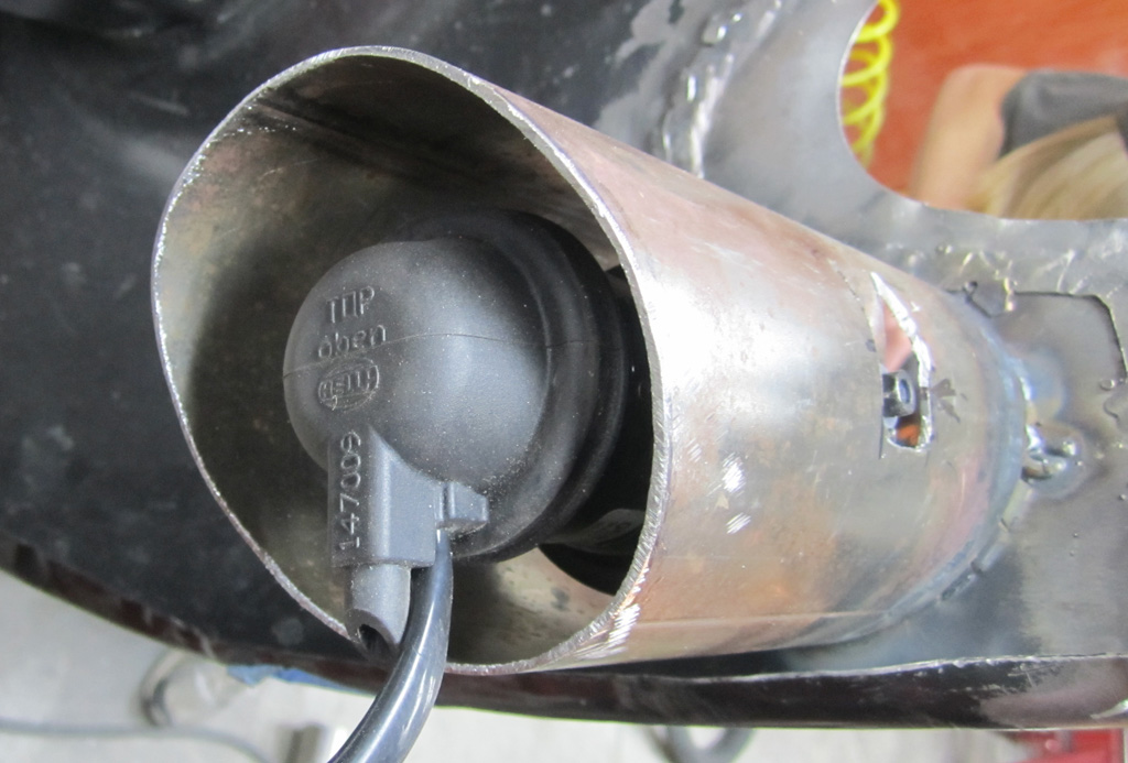
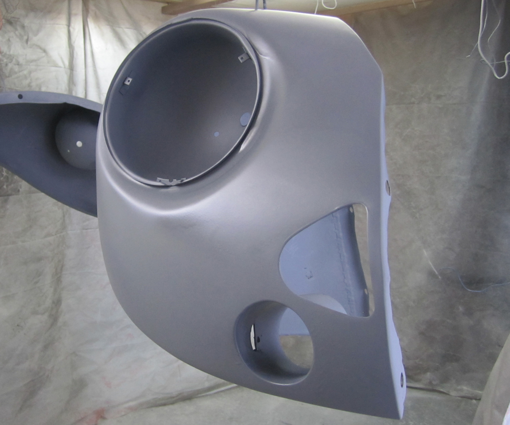
To make them not look "added on" we purchased some 3 1/2" exhaut pipe at our local Napa store, and marked the location:
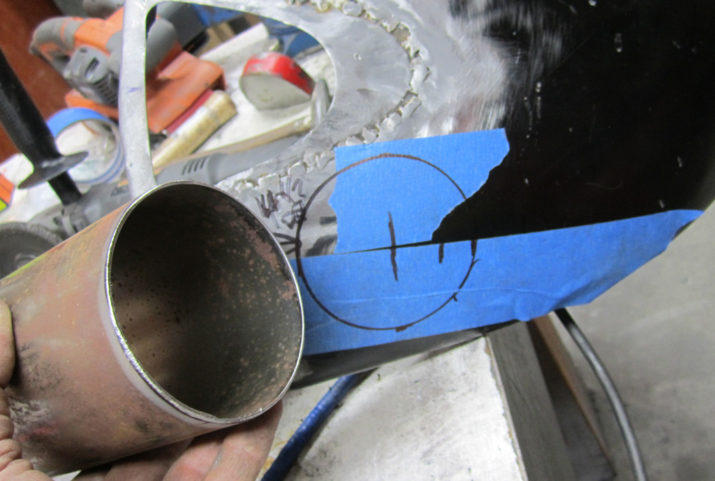
We then cut out a central hole, and radially cut to the outside marked line:
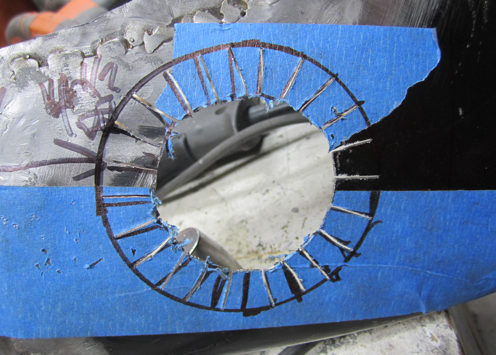
We took a short piece of the 3 1/2" pipe, cut a slice out of the side, and "shrunk" it until it would fit inside the tabs. Then wile holding it straight and level,we marked it:
And then cut it:
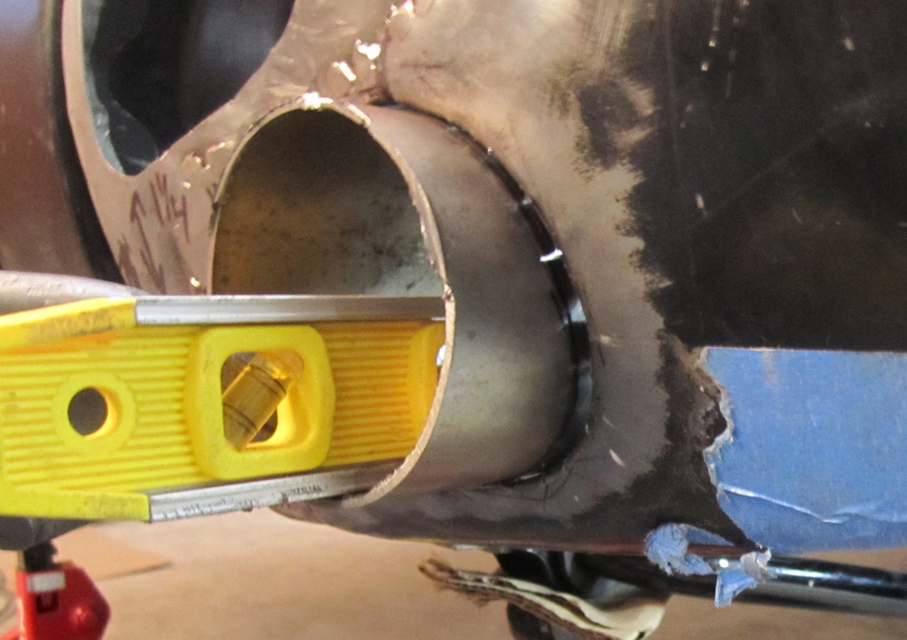
Now we have a template of the end profile that will match up with the fender's curve. Notice that we used the welded seam of the exhaust pipe to indicate the center top. Slip the smaller, split pipe inside the final piece of pipe and mark the profile:
Cut the outer pipe along the line, discard the inner marker pipe, then we can slip the pipe over the tabs from the abck side and tack weld it in place, checking for level and straight:
At this point we checked the fit by spacing the light in the pipe with some folded cardboard:
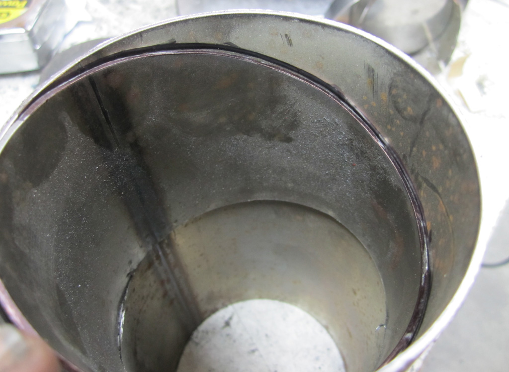
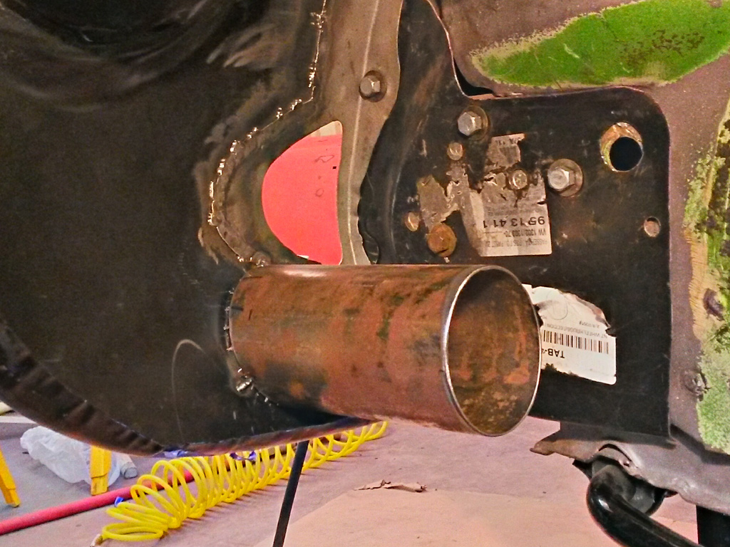
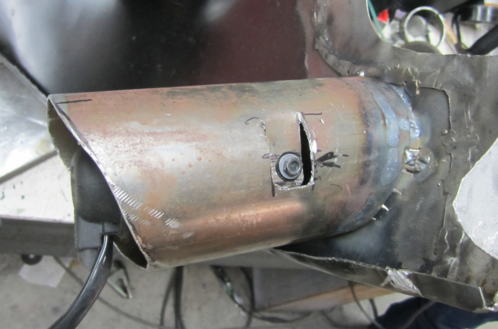
We then welded the tabs to the inside of the pipe, and cut & drilled some mounting tabs. The bolts that come with the lights are self-tapping affairs that I am not fond of. Since this photo we have re-tapped the holes in the lamp body with 1/4-20 at full depth, and have nice stainless screws to hold the, together:
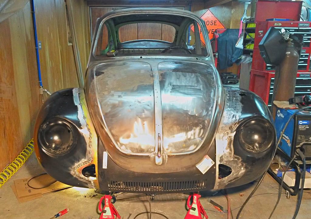
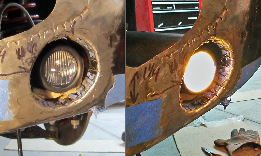
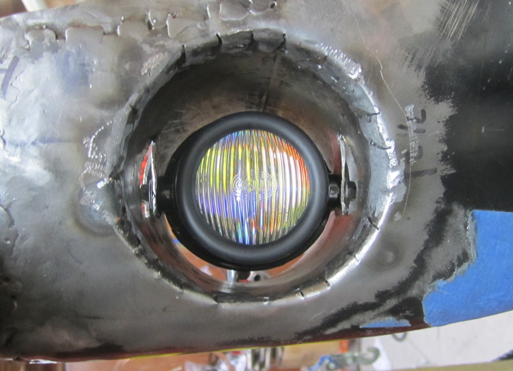
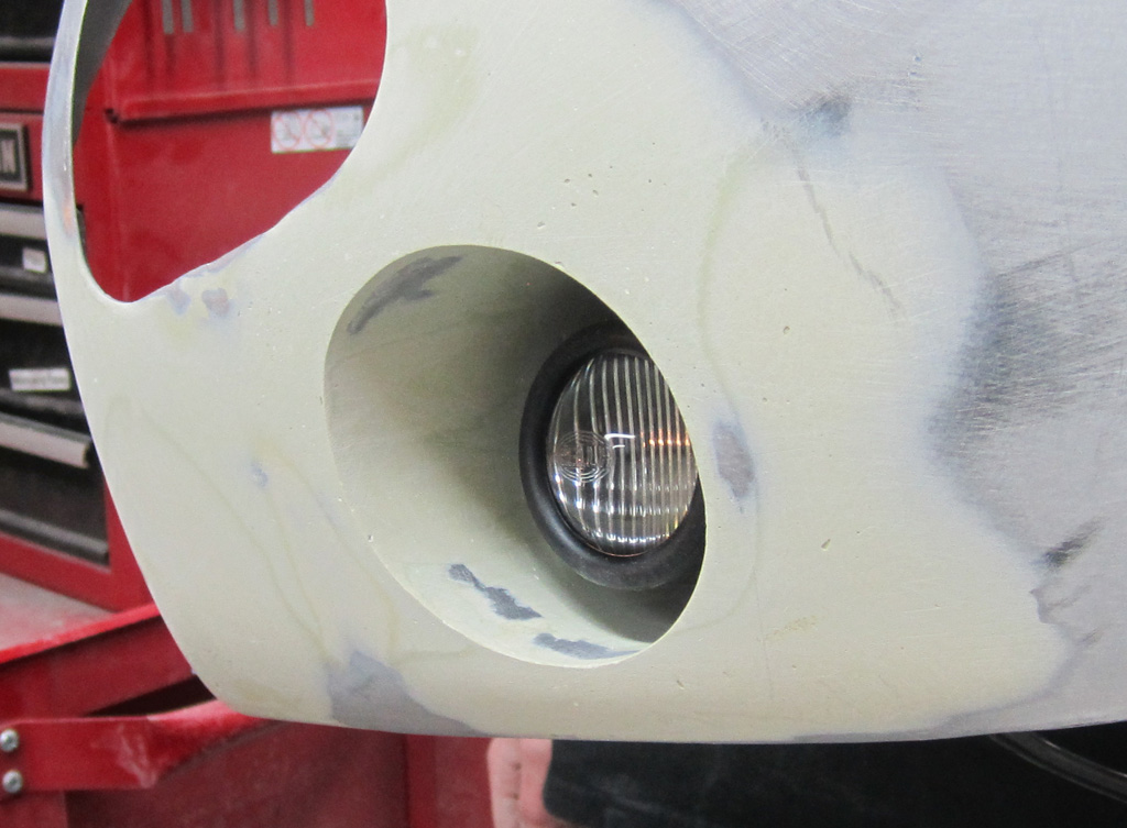
Here is a shot from the front. There is a lot more metal finishing needed, of course. You can see the dichroic yellow and blue hints from the PIAA bulb. The clearance around the bulb should allow air to blow over it and keep it cool:
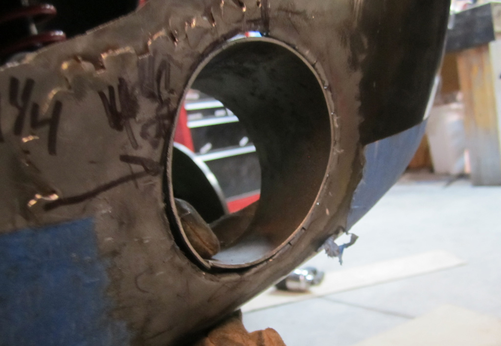
A shot from the back. The extended pipe will protect the lamp from gravel thrown by the wheel. It appears to have plenty of clearance to the tire, even though the pipe looks really long:
Here is our quick check to see if they are even close to symetrical:
We still need to do the final metal work, then 2K primer and the bondo. (Why am I so embarassed to say "bondo"? It will not be very thick and I am just not that good of a metal worker to make it perfect without filler.)
In other news, we picked up a "basket case" 1975:
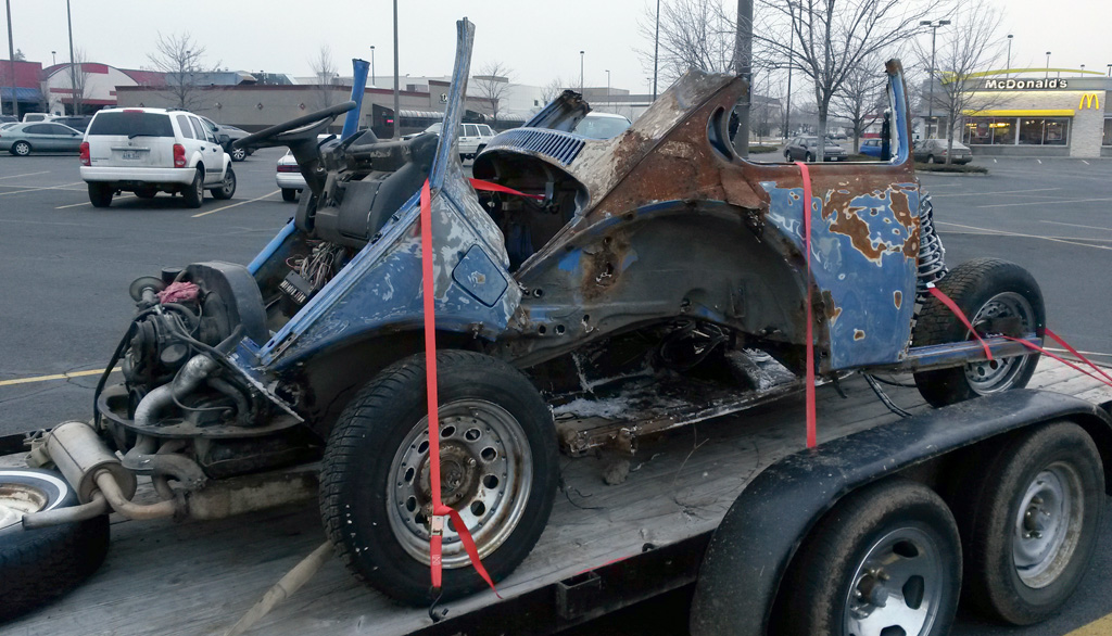
We went to the place to look at the doors and the hood, but they were not much better than the ones we had. Supposedly the engine was running when it was parked (he was gonna "fix up" the car). After talking a bit we decided to go ahead and get it for parts. Not that we need more parts. Wait . . . why did we drag this thing home?
We thought we could sell the engine, transmission, speedometer, seats, wheels, starter, fuel tank, rack&pinion and whatever else was not ruined and come out about even - we paid $280 for the whole pile and there is a second load in the back of the pickup, not shown here.
One nice thing is that the engine (likely original, rebuilt only once according to the stack of receipts and original owners manual) appears to be complete, and will turn over. There is the computer for it, injectors and the works:
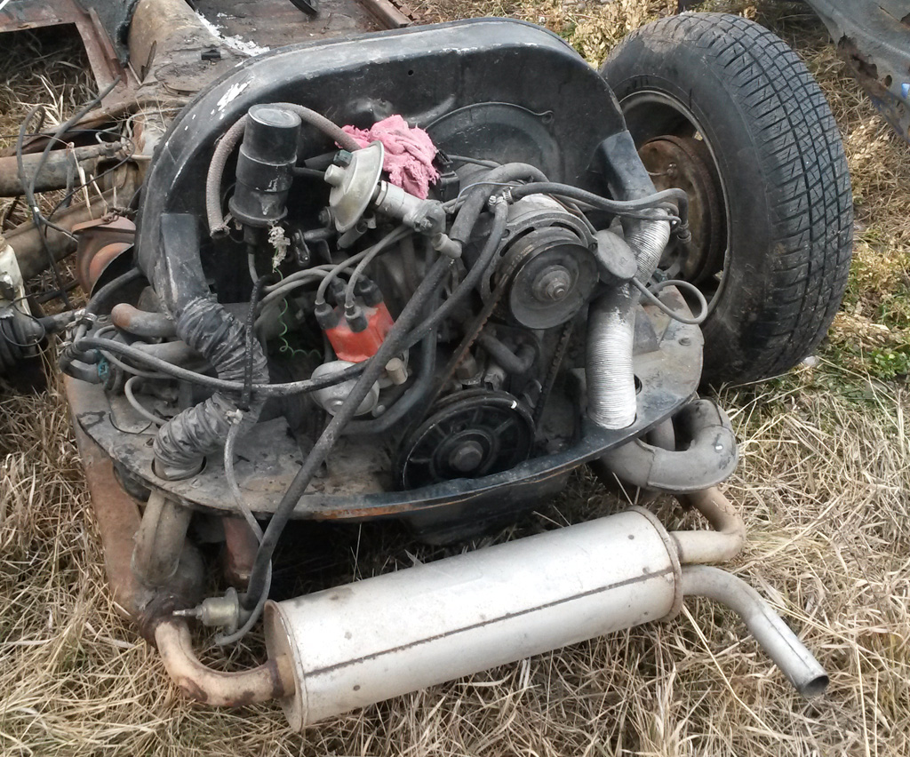
On closer inspection, the engine gave up a potential nice little surprise: an AS-21 case:
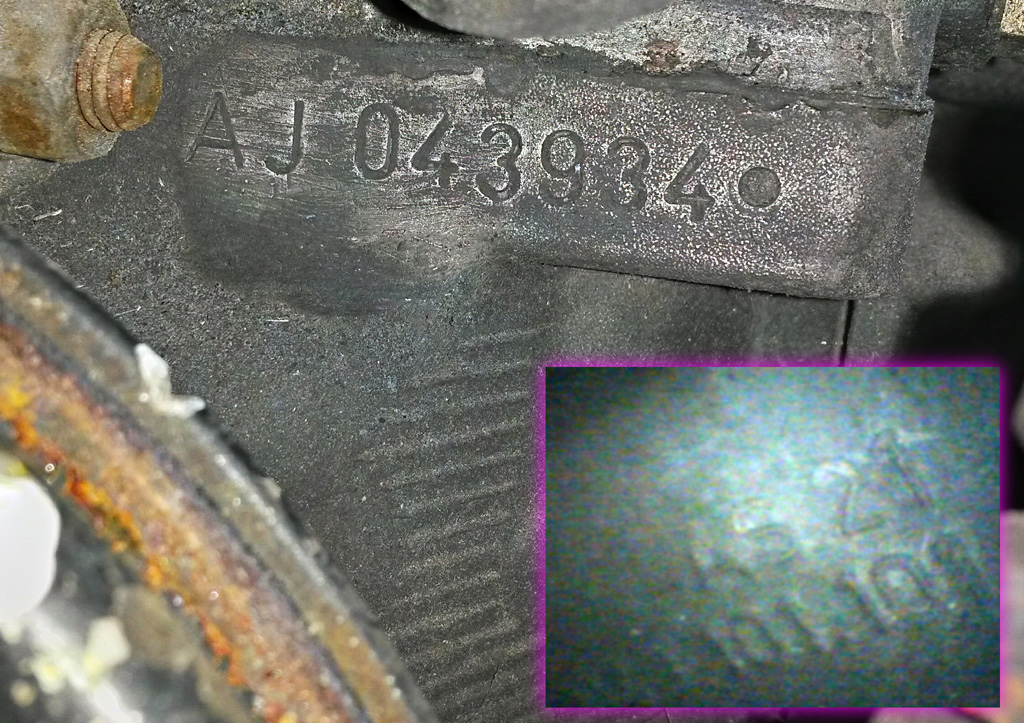
Also nice: 4 matching serial numbers and a clear title. And it is the Ancona blue that he decided to go with. So if we were willing to swap pans we could have a "original" restore. Something to think about.
Comments welcome. Should we have left it to rust?
Last edited by Baxsie on Fri Aug 08, 2014 11:52 am; edited 1 time in total |
|
| Back to top |
|
|
Doodoob
Joined: 06 Jul 2011
Posts: 98
Location: Spokane, WA
|
| Posted: Fri Jan 24, 2014 8:56 am Post subject: |
|
|
| If the case is good and not trash you got a good deal. Everything else you sell of is just extra. I did a quick search and couldn't even find any AS21 cases for sell. |
|
| Back to top |
|
|
Baxsie
Joined: 12 Apr 2012
Posts: 253
|
| Posted: Sun Feb 02, 2014 8:42 pm Post subject: Removing the Gas Flap / Door Finger Notch |
|
|
Doodoob>If the case is good and not trash you got a good deal. Everything else you sell of is just extra. I did a quick search and couldn't even find any AS21 cases for sale.
I think we will try to fire it up when the weather is nice. It would be easier to sell and safer to buy if we knew it runs.
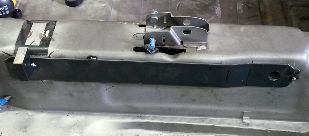
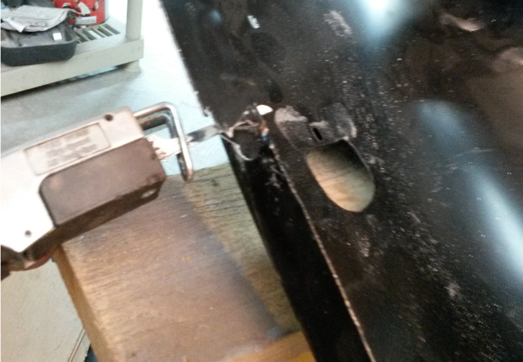
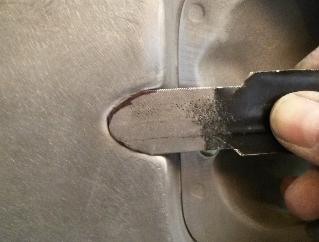
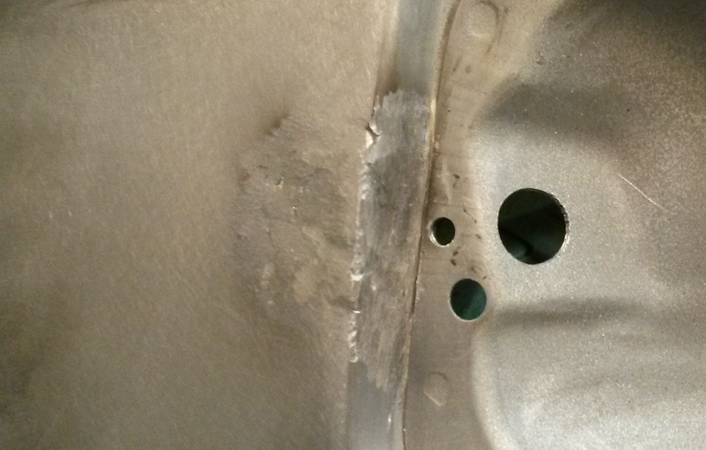
As detailed long ago (in "Making Gas Door Release Inside Again"), we put a latch on the gas door, so we would not have to mess with locking gas caps. At the time, I thought I would leave it to the body shop to fill in the finger notch, but we are getting a bit braver so I thought I would give it a shot on my own.
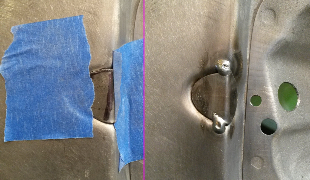
We started with some spare bod metal shaped to fit the opening:
Bent that so it filled the notch:

Used some tape to hold it in place and tack welded:
Then made several short welds to complete it, allowing full cooling between:
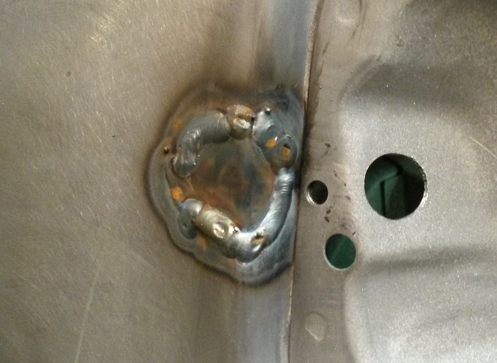
We used the carbide burr in an air powered die grinder to smoothe the welds out:
Here is the first pass on the bondo. I am a bit surprised how far the bondo goes beyond the weld until it feathers. I guess that the welding must have warped things down a bit, despite my attempts to keep things cool. I used a long block sanding block to make sure I followed the plane of the panel. The center of the sanded bondo is still a little low:
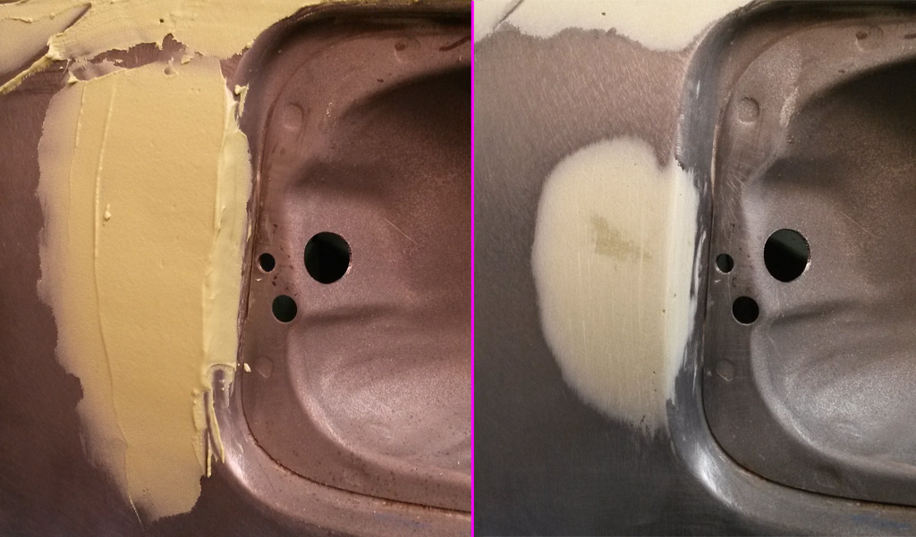
A quick test fit with the gas flap:
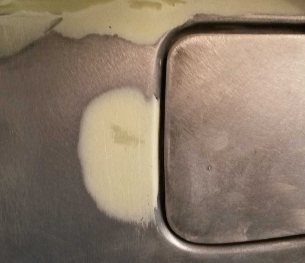
And a final picture after the second shot of bondo is sanded smooth:
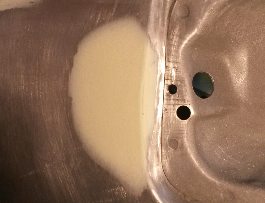
Nice way to spend a couple of hours in the warm shop on a cold Saturday.
Last edited by Baxsie on Fri Aug 08, 2014 11:52 am; edited 1 time in total |
|
| Back to top |
|
|
ONEBADBUG

Joined: 25 Oct 2003
Posts: 440
Location: Spokane
|
| Posted: Sun Feb 02, 2014 9:58 pm Post subject: |
|
|
| You guys are completely mental! I love it. |
|
| Back to top |
|
|
Baxsie
Joined: 12 Apr 2012
Posts: 253
|
| Posted: Sun Feb 09, 2014 8:26 pm Post subject: Making Super Beetle Front Fenders Wider - Filler & Prime |
|
|
It has been quite a learning experience on making these fenders wider (Skip back to here to see the start of the fender widening). We have done a few things right the first time. Mostly, however we get things right after several tries. Lots of pounding, grinding, etc. Lots of doing things slow that should be fast.
We finally got the filler close enough to brave showing it to the body shop who will do the final painting. He said "it was better than he expected". He gave us a bunch more tips and strategies and back we went for more work on the fenders. More blocking, "pecking" at the highs spots, skim coats, sanding, blocking . . . here are the results:
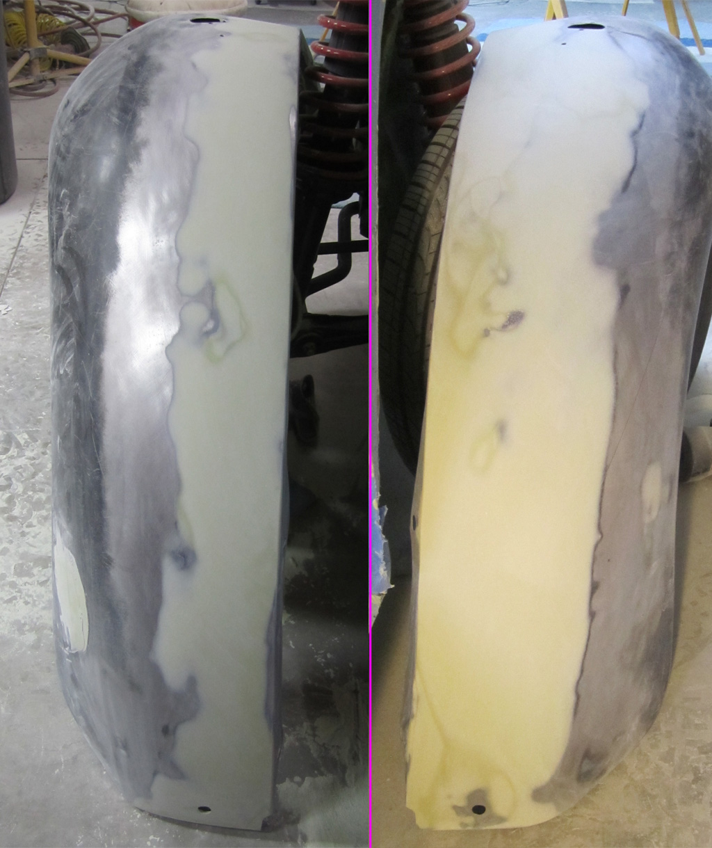
Today we went ahead and shot the fenders with the 2K epoxy primer to cover the bare metal and seal the filler. There are some small flaws, but the magic of the camera hides most of that:
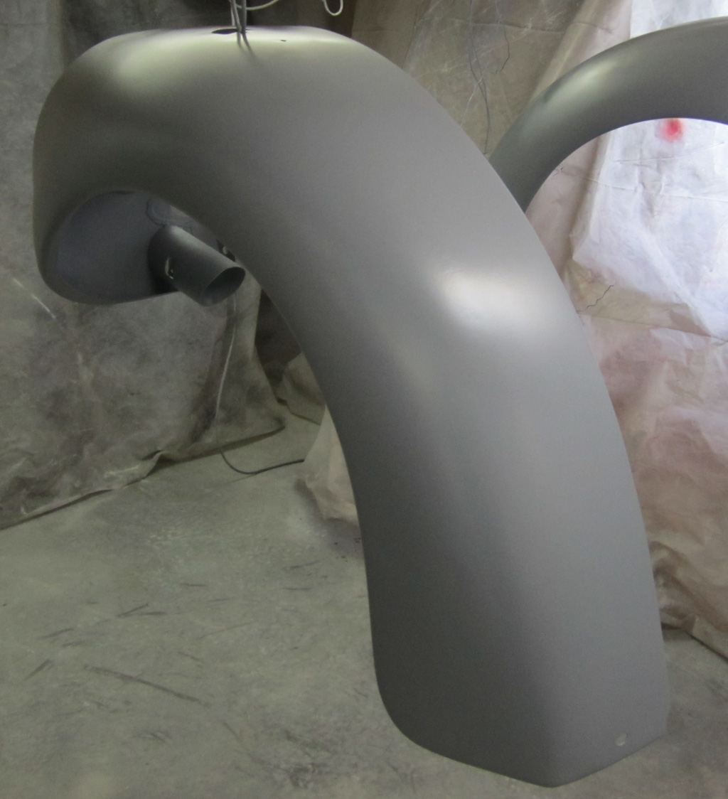
We then shot over the 2K epoxy primer with some sandable primer. Next will be a guide coat and more blocking.
Last edited by Baxsie on Fri Aug 08, 2014 11:51 am; edited 1 time in total |
|
| Back to top |
|
|
Baxsie
Joined: 12 Apr 2012
Posts: 253
|
| Posted: Tue Feb 11, 2014 10:36 pm Post subject: Making Super Beetle Rear Fenders Wider - Marking |
|
|
| ONEBADBUG wrote: | | You guys are completely mental! I love it. |
I'm just gonna take that as a compliment . . . I think . . .
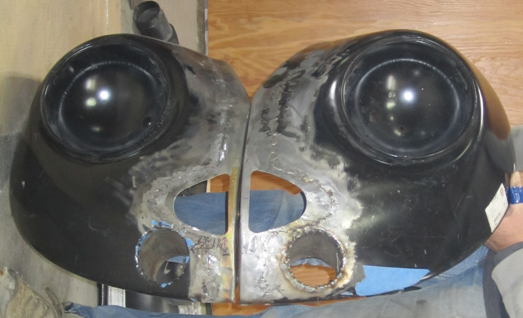
Fresh off the relative success of the front fender widening project, we decided to tackle the rear fenders. The front fenders meet the body at nearly a 90 degree angle along most of their length so moving them outward was relatively simple. In contrast, the rear fenders meet the body at a pretty good slope along much of their length.
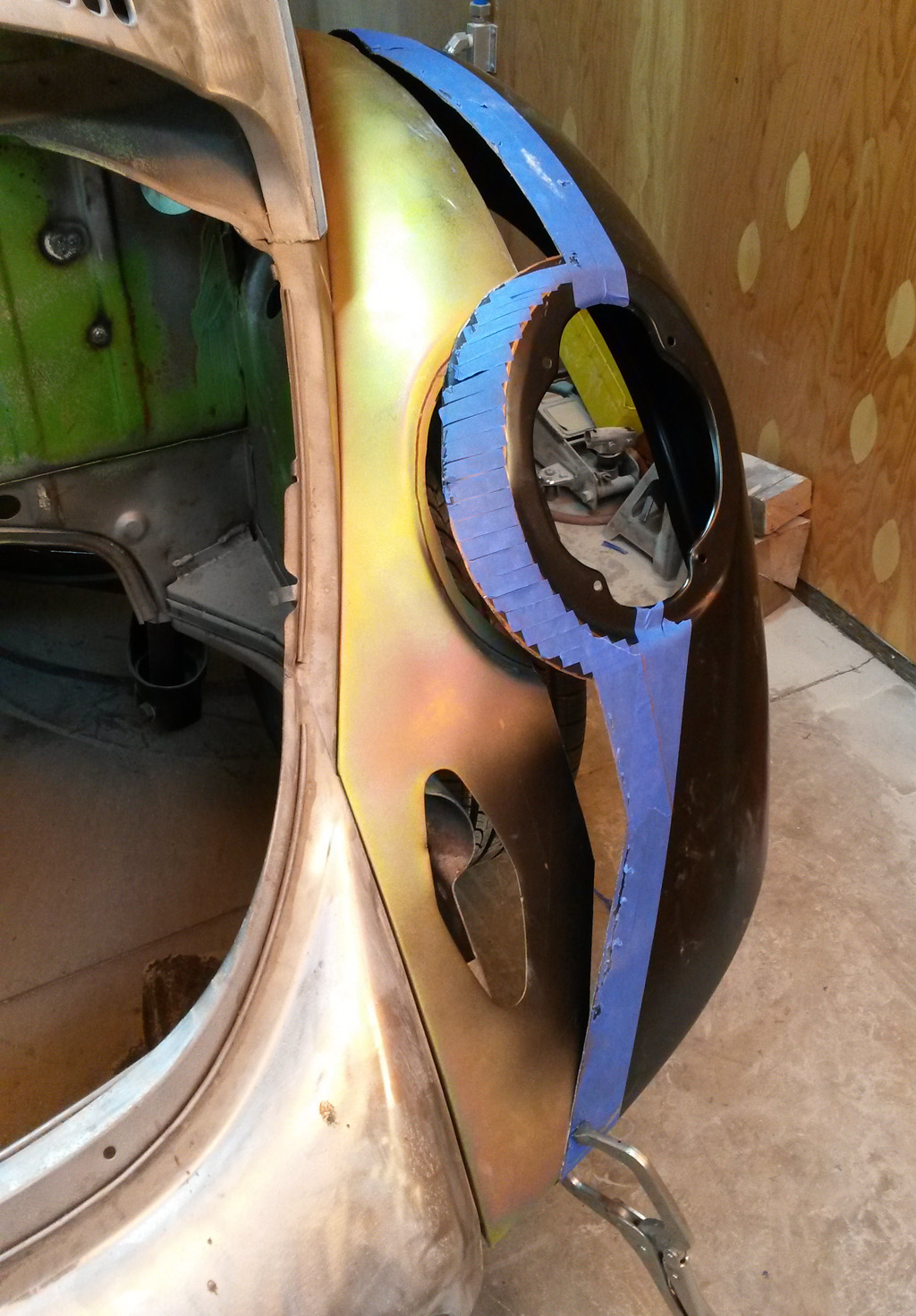
After quite a bit of head scratching, we have the fenders marked for cutting like this:
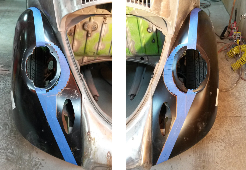
The inside of the tape will be the outer fender cut line, the outside of the tape will be the inner fender cut line:
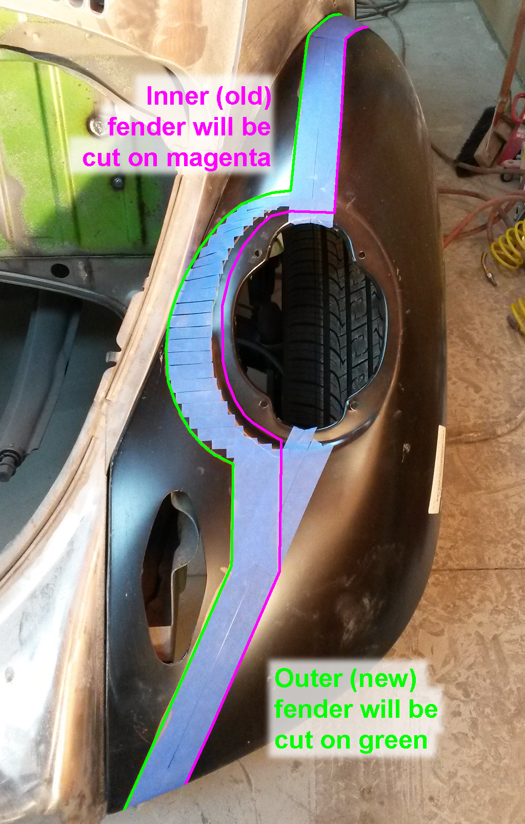
The bumper hole will be entirely on the inner fender, so that geometry will not get messed up. The tail lights will move out and be entirely on the outer fender.
We duplicated the marking on a total of four fenders:
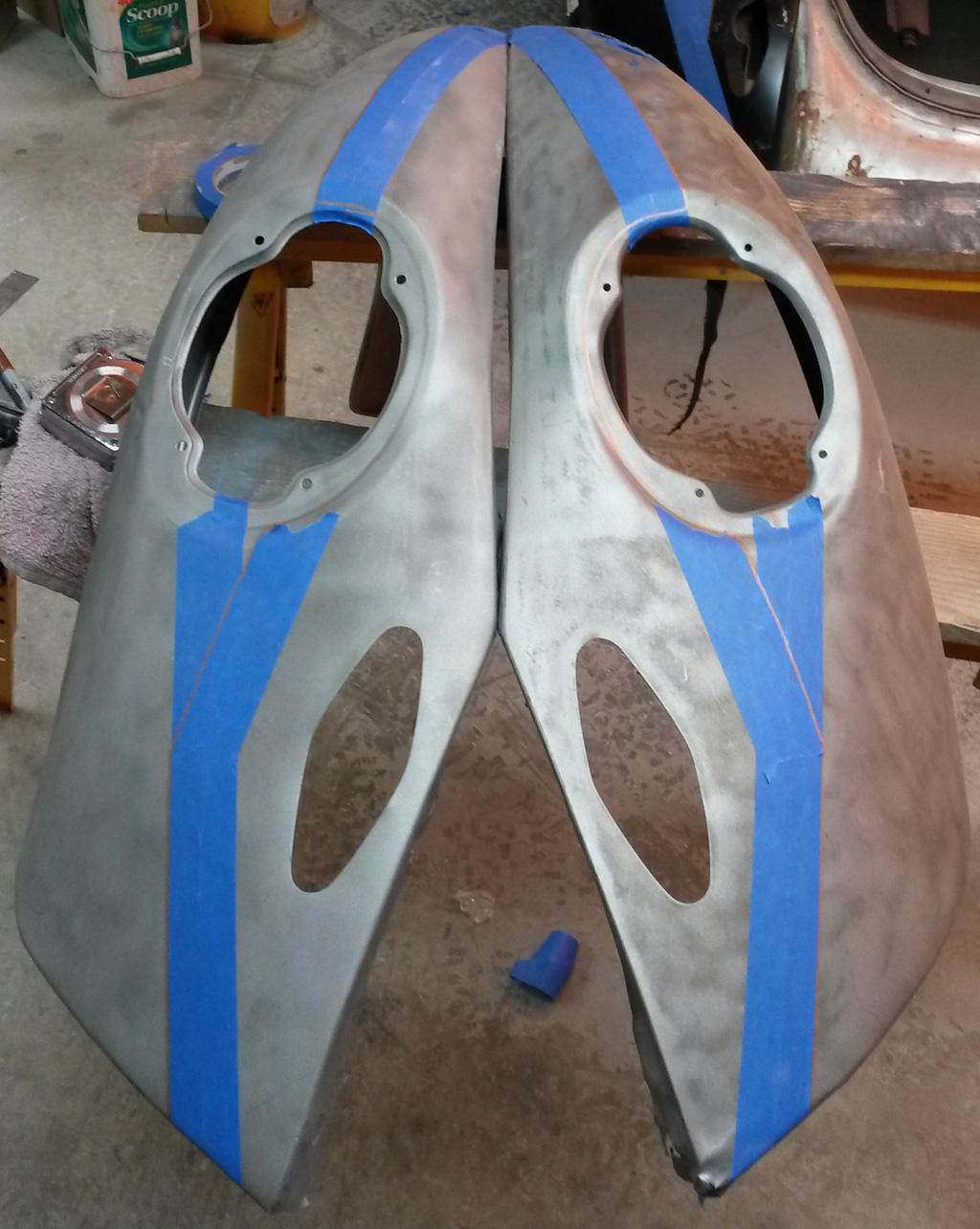
The right fender is in pretty bad shape, and as we left the shop, I noticed we have another right fender in better shape, so we will probably end up marking one more.
Last edited by Baxsie on Fri Aug 08, 2014 11:51 am; edited 1 time in total |
|
| Back to top |
|
|
Baxsie
Joined: 12 Apr 2012
Posts: 253
|
| Posted: Thu Feb 13, 2014 9:54 pm Post subject: Photo of wider front Super Beetle Fenders Installed |
|
|
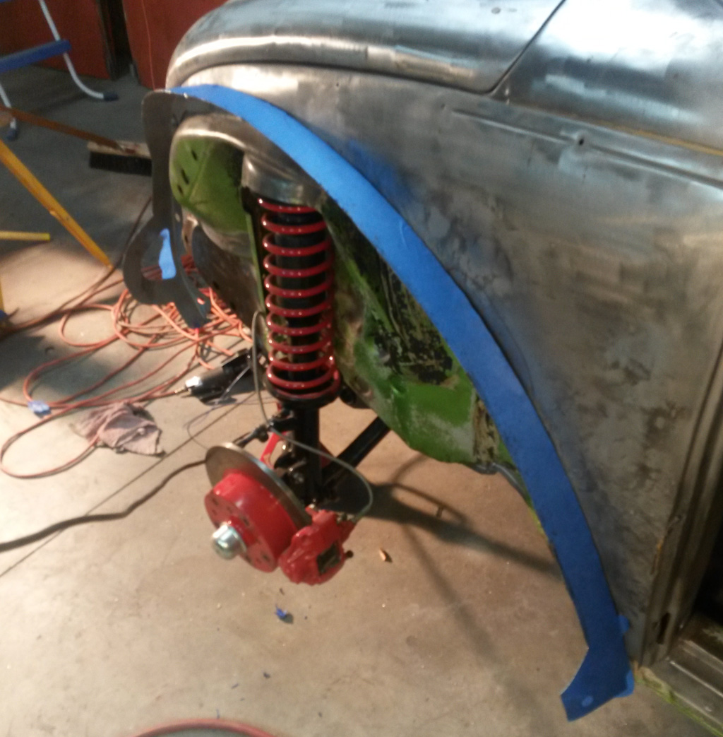
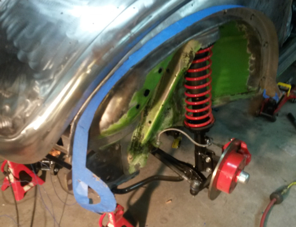
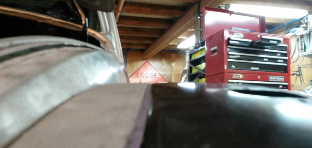
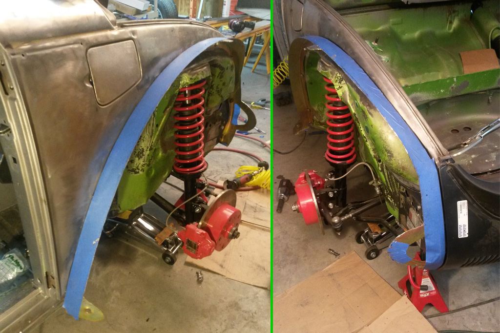
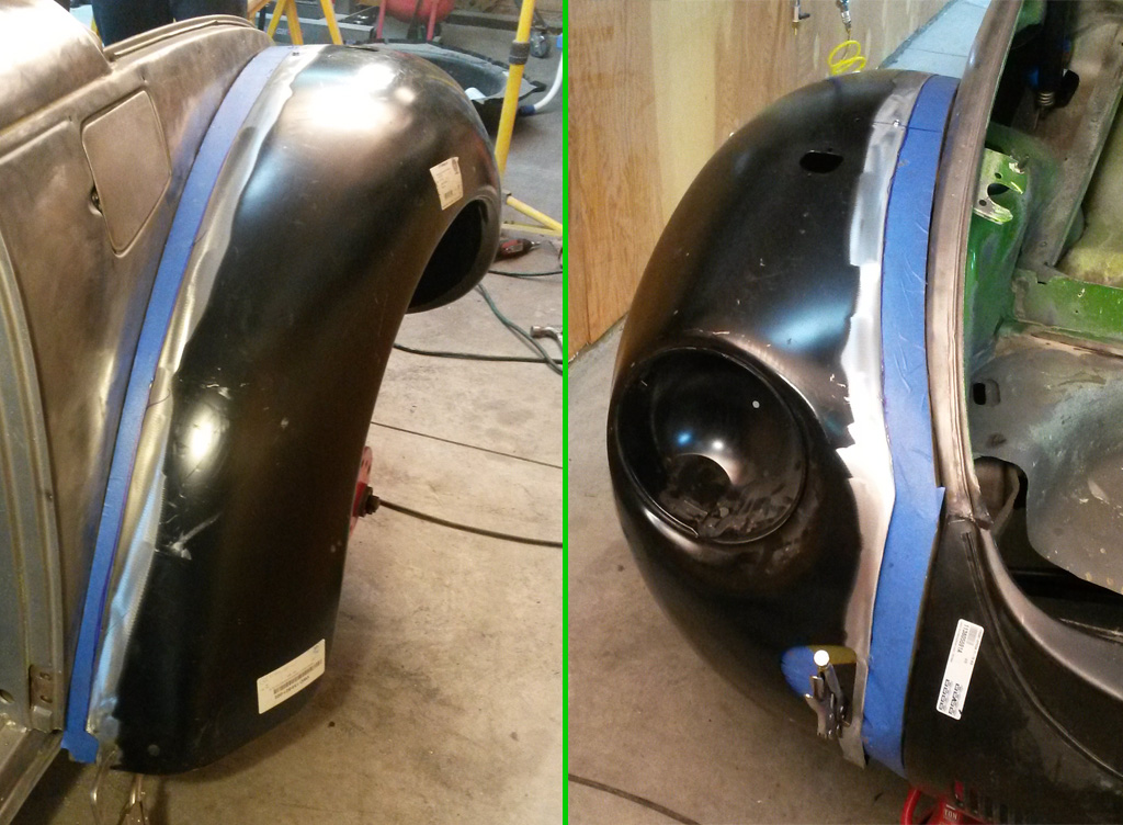
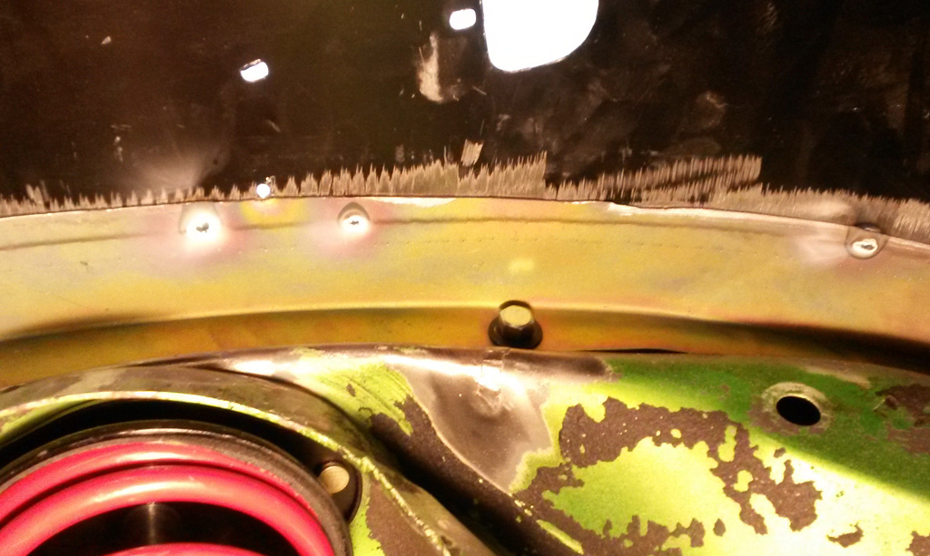
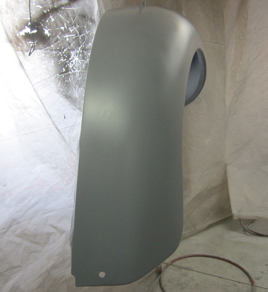
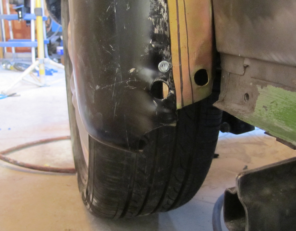
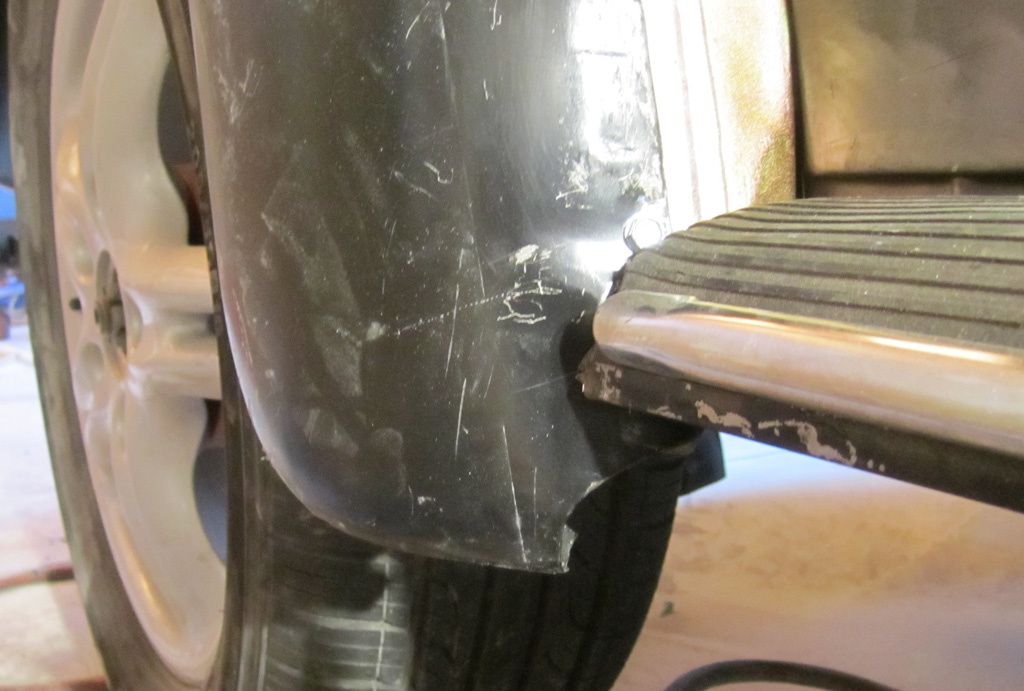
We mounted the primed fenders so we could measure the finished distance from the fender lip to the tires. Looks like ~1 1/4 to ~1 1/2 depending on where you measure. We wanted to make sure the rear fenders had about the same amount. Took a photo from the front while we were at it:
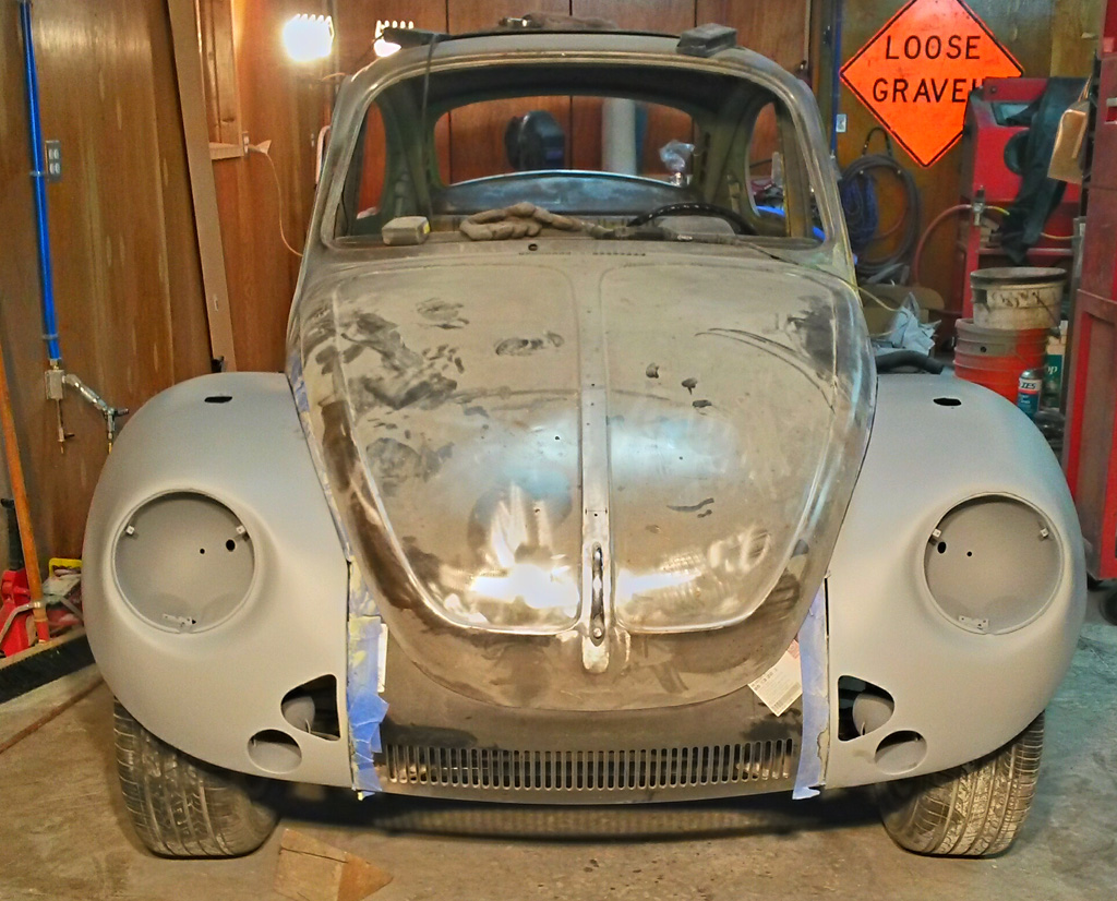
We test fit the running board to make sure that would not be an embarrassing fit. I think it looks pretty good:
Last edited by Baxsie on Fri Aug 08, 2014 11:50 am; edited 1 time in total |
|
| Back to top |
|
|
Baxsie
Joined: 12 Apr 2012
Posts: 253
|
| Posted: Thu Feb 13, 2014 10:12 pm Post subject: Making Super Beetle Rear Fenders Wider: Cutting and Test Fit |
|
|
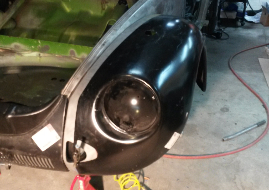
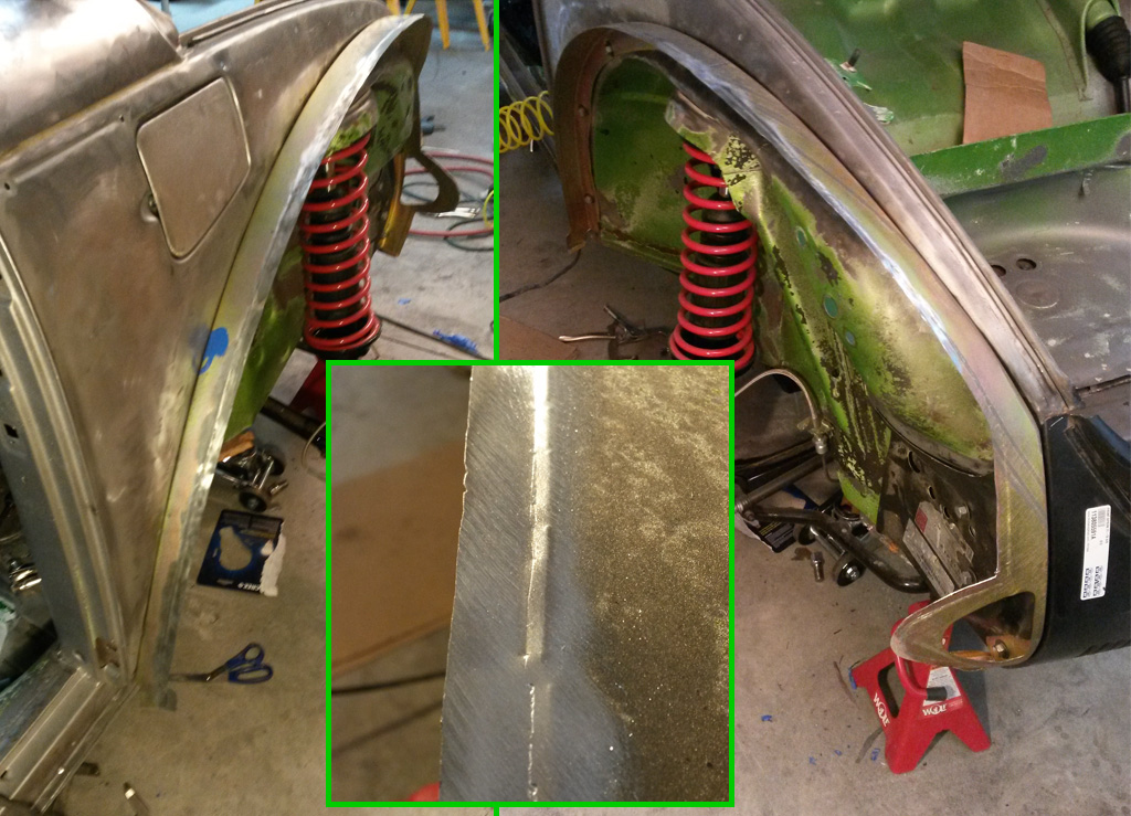
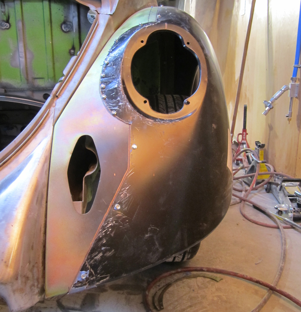
We cut along the lines indicated on the post above, and quickly slapped the two together. Looks pretty hopeless:
We then used sheet metal screws to adjust and tweak the position, not looking so bad:
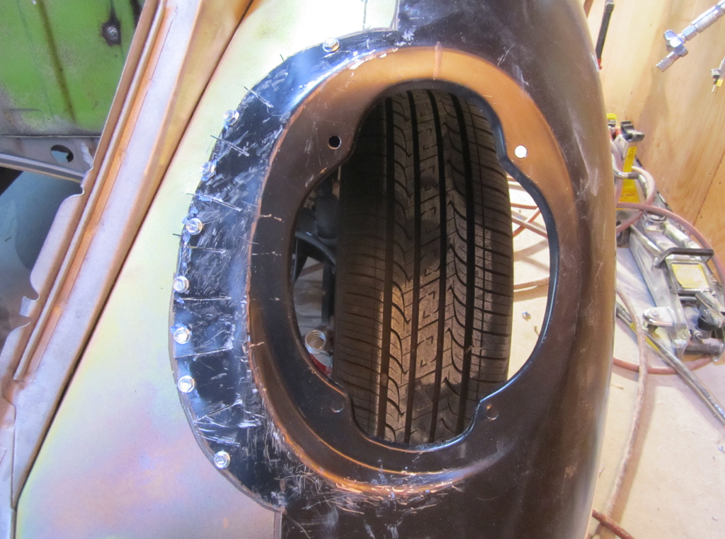
We aligned the new and old fenders based on marking from the top-most fender hole. Oddly, the rear edge lines up very nicely:
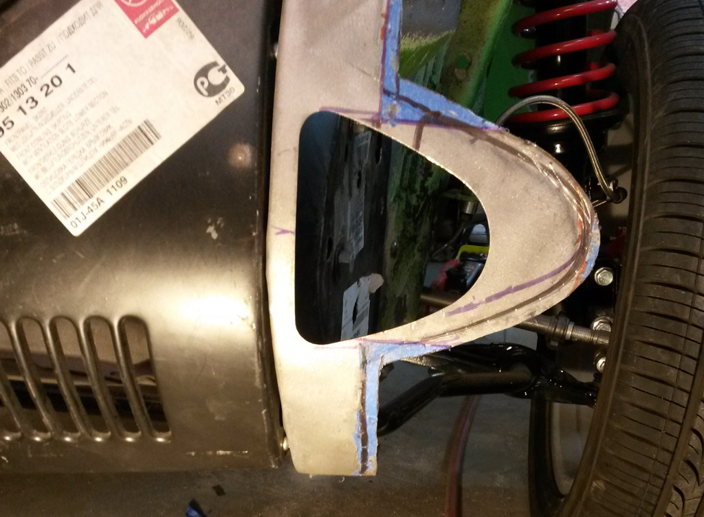
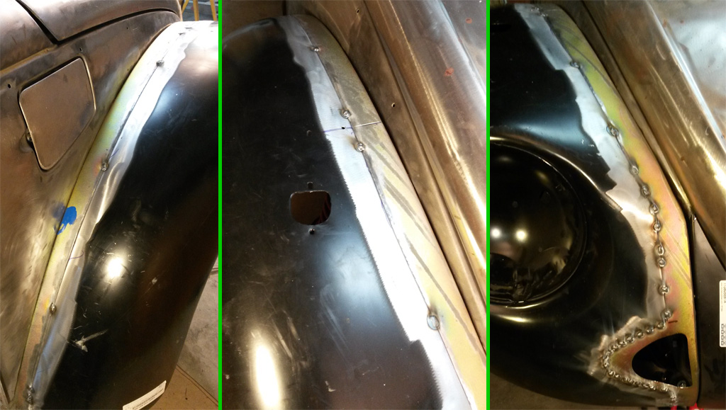
After we made some radial cuts, the tail light area actually lay down quite well. The upper-left quadrant is "high", so we will need to adjust that in before welding, and the area between the tail light opening and the bumper strut opening is "low" so again that will need to be bumpped out before welding:
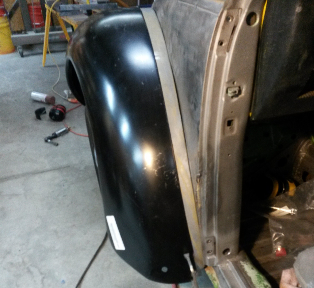
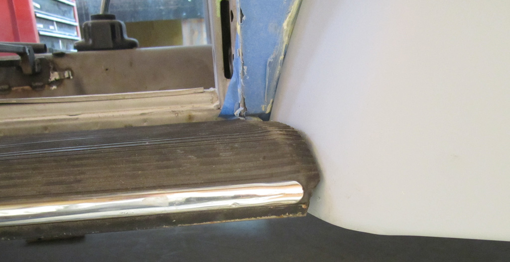
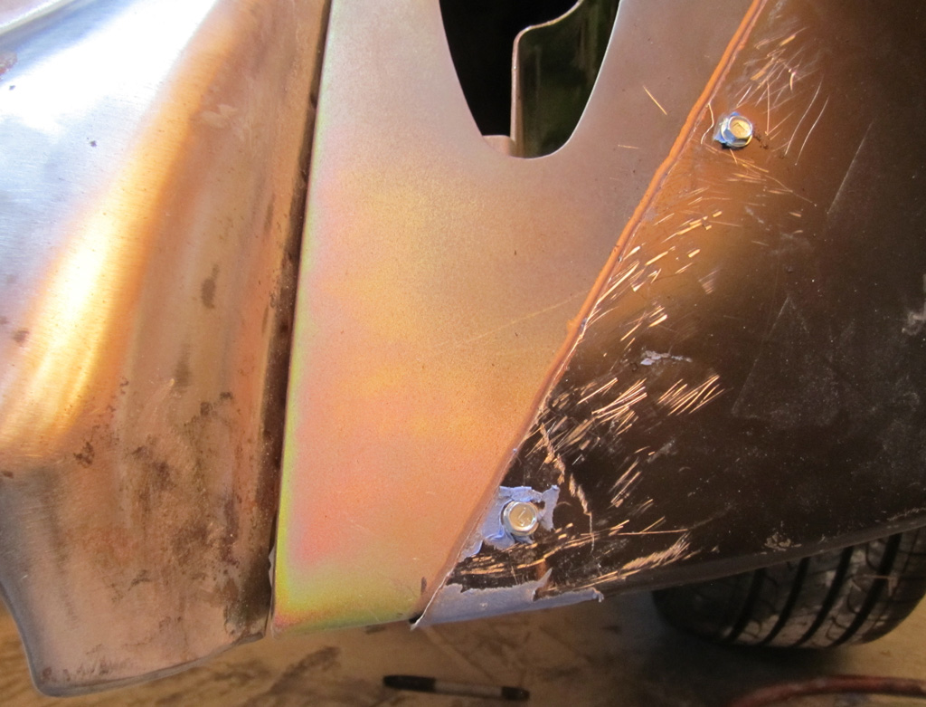
The front edge appears to be way too long:
It does not line up with the running board at all very well. I need to look at how this area is on a factory car so we can shorten the fender if needed:
Last edited by Baxsie on Fri Aug 08, 2014 11:50 am; edited 1 time in total |
|
| Back to top |
|
|
|
|
You cannot post new topics in this forum
You cannot reply to topics in this forum
You cannot edit your posts in this forum
You cannot delete your posts in this forum
You cannot vote in polls in this forum
You cannot attach files in this forum
You can download files in this forum
|
|