| View previous topic :: View next topic |
| Author |
Message |
Baxsie
Joined: 12 Apr 2012
Posts: 253
|
 Posted: Fri Aug 08, 2014 5:21 am Post subject: Making 1975 Gas Door Work With Old Wide Stainless Chrome Posted: Fri Aug 08, 2014 5:21 am Post subject: Making 1975 Gas Door Work With Old Wide Stainless Chrome |
 |
|
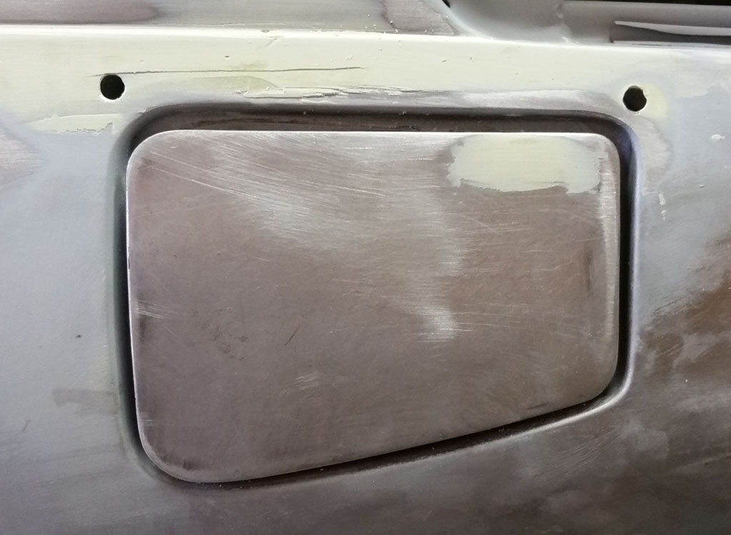
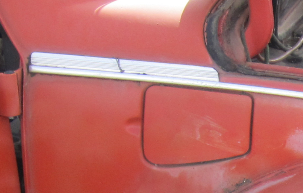
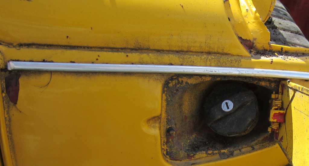
Previously, we had converted the gas door to an inside latch, and removed the finger notch.
We wanted to use the old-school wide stainless trim, but by the gas door the trim was right on the edge of the opening, maybe hanging over a bit. We noticed that the upper and lower gaps on the gas door were large compared to the sides, so we moved the door down until the bottom gap matched the front and rear gaps:
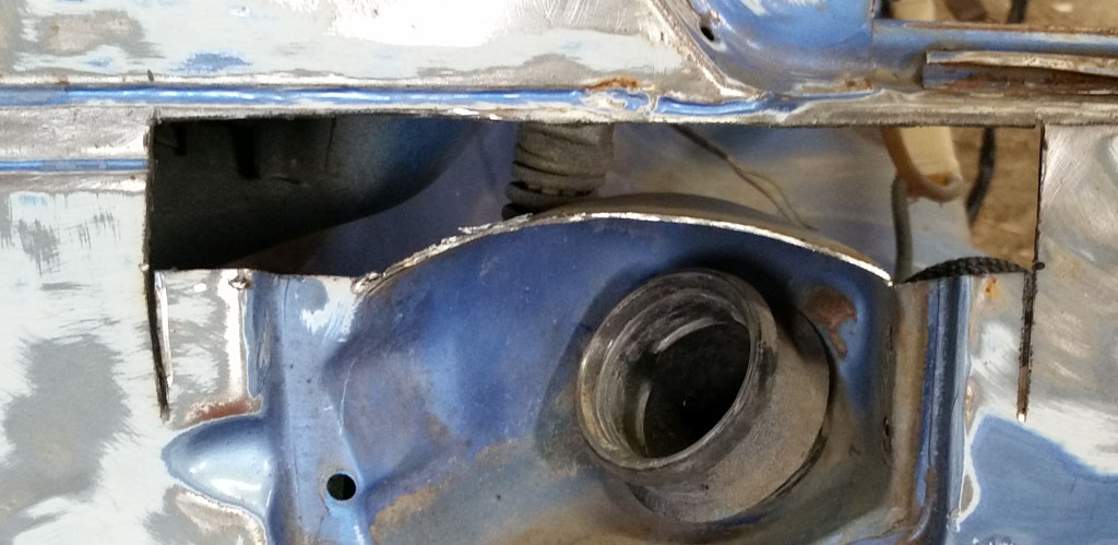
We then cut a patch from the basket case:
After cleaning the patch, we did a test fit to see if this idea might work. Looks encouraging:
We then trimmed the patch piece to just the tiny sliver we will use, and did a test fit:
Then welded:
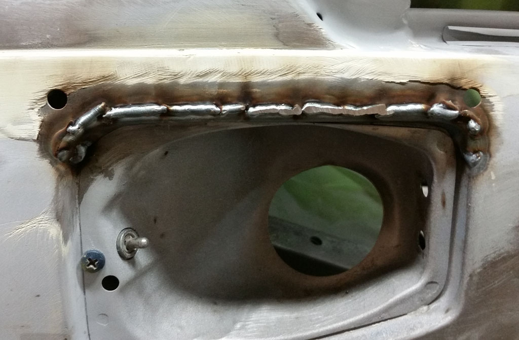
Slowly, my MIG welds are getting better:
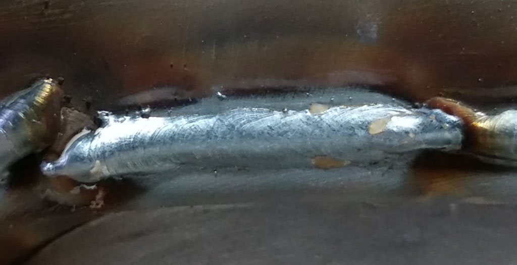
Then knocked the weld beads off using the die grinder:
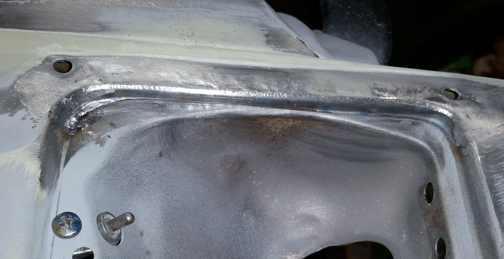
And a quick test fit with the gas door:
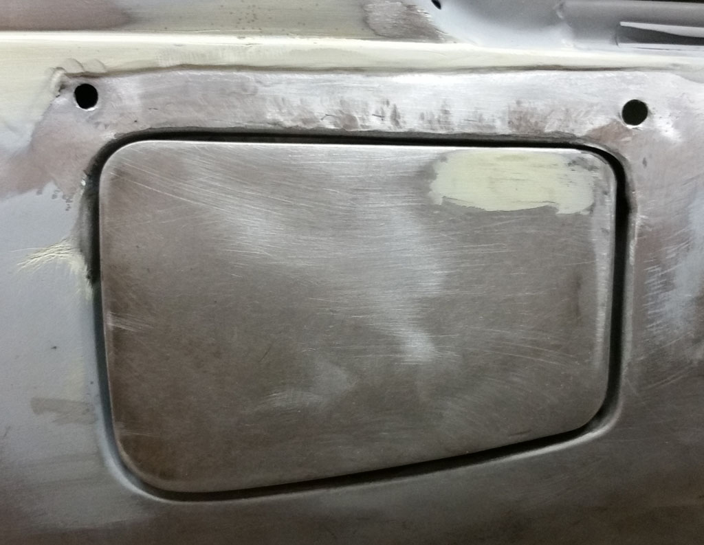
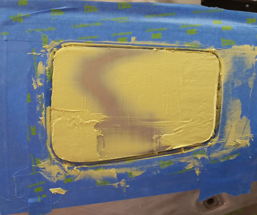
Then fill and sand with body filler:
[img]http://baxsie.com/images/forum/bug/white_75/Gas_Door_Opening/10_Slobbering_On_The Body_Filler.jpg[/img]
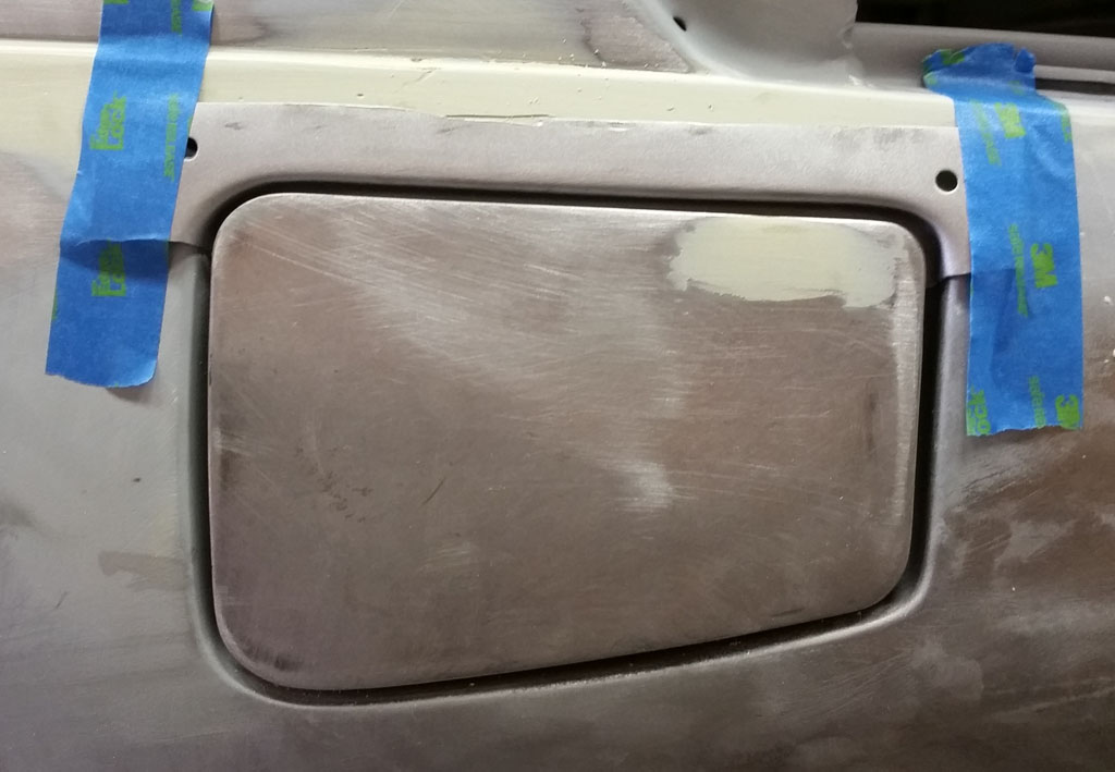
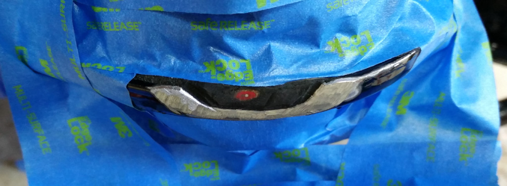
Checking the chrome shows a nice little step of body below the chrome above the door:
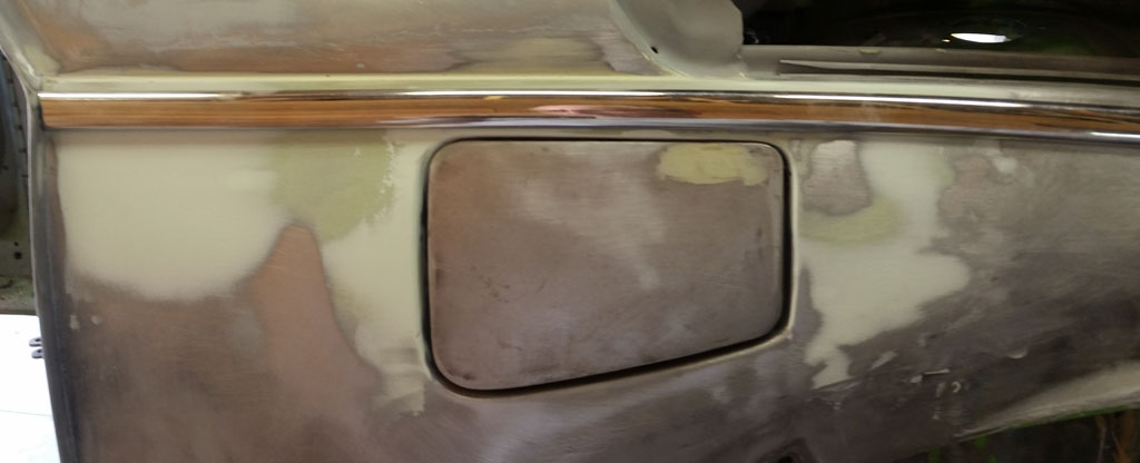
The contour of the gas door does not quite match the body. We decided to try to use a straight edge and bondo to force the to match:
We then rough sanded the bondo, and skimmed the door with metal glaze, followed by linear sanding and block work.
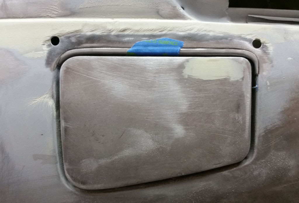
Final shot, getting close to ready for prime:
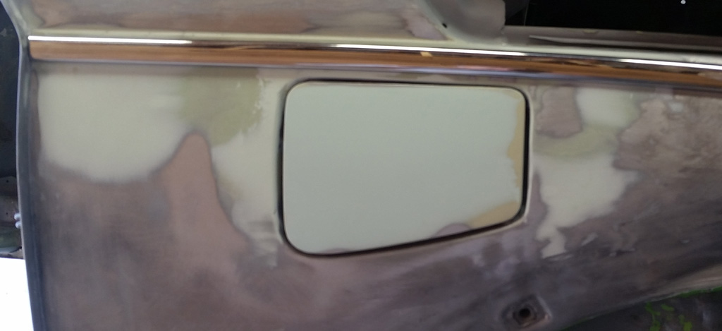
You might notice that we extended the body line of the hood/fender back to the door, getting rid of that horrible hack piece of extruded aluminum trim:
That was added to cover up the longer body weld (brazing, actually) on the 1303 curved window supers:
 |
|
| Back to top |
|
 |
Baxsie
Joined: 12 Apr 2012
Posts: 253
|
| Posted: Fri Aug 08, 2014 5:22 am Post subject: New Tubing For Sliding Steel Sunroof Drains |
|
|
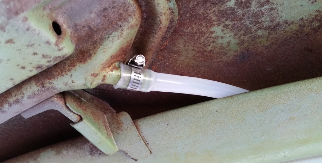
The old tubing for the sunroof drains was still intact, and in pretty good condition, but where it connected to the metal tubes, it was kinda loose, and one of the rear ones was cut off short.
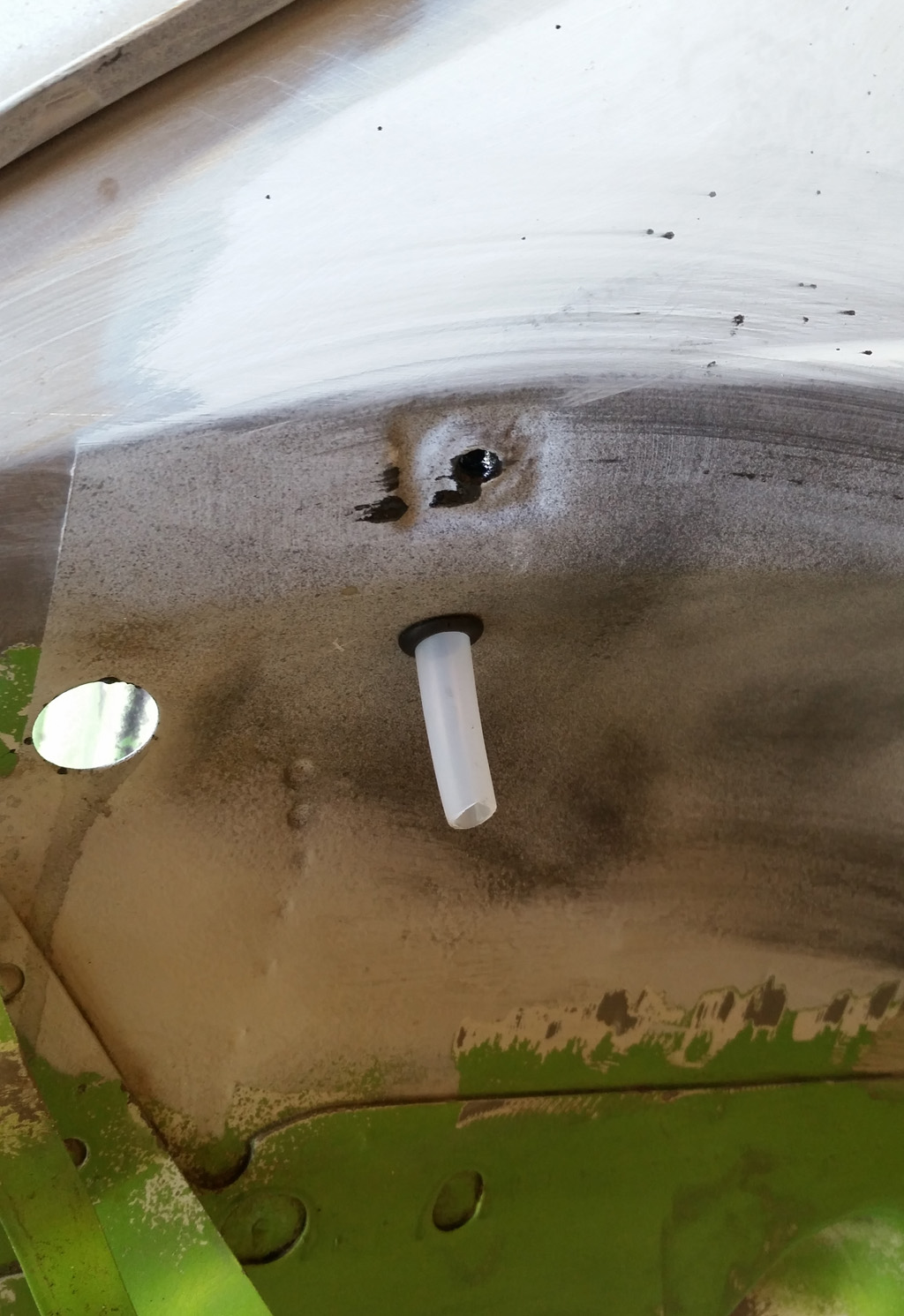
We got some polyethelene tubing at Home Depot, used the heat gun to gently warm it up to where we could work it over the metal tube and then secured it with a clamp:
For the front two runs, we just followed the factory routing, and the sunroof will drain into the body and from there hopefully through the drain holes and onto the ground.
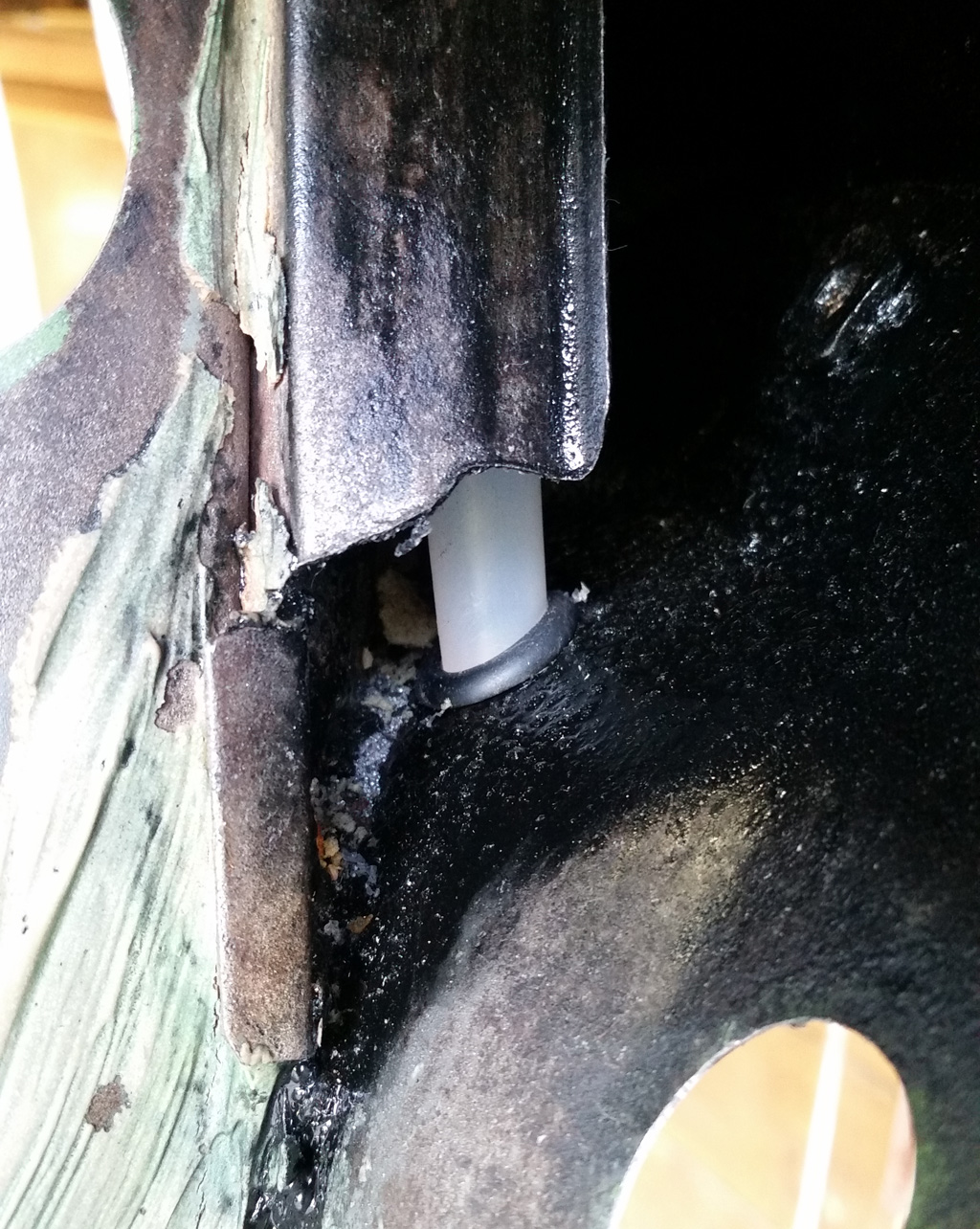
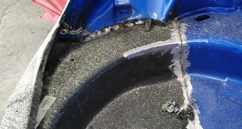
For the rear runs, the hose was still embedded in more of that darn foam of death. We found that by relentlessly twisting the tube in a single direction, it will collapse on itself and pull out of the foam. The new tubing in the back follows about the same path as the original, but instead of dumping out into the engine compartment as the original did:
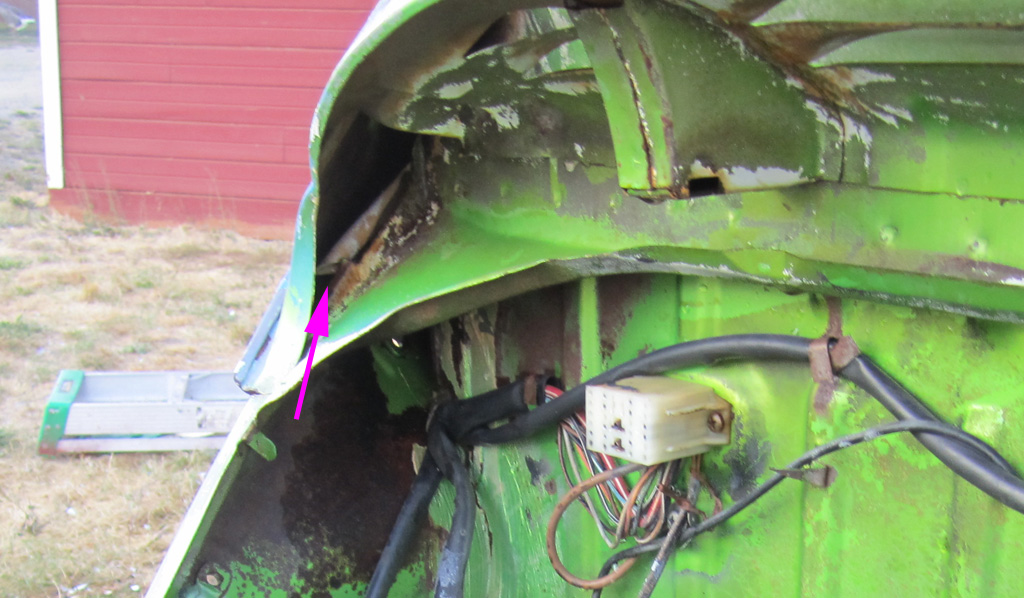
We diverted it and made it drain into the wheel well:
 |
|
| Back to top |
|
|
Baxsie
Joined: 12 Apr 2012
Posts: 253
|
| Posted: Fri Aug 08, 2014 5:23 am Post subject: Getting ready to paint the inside of the body |
|
|
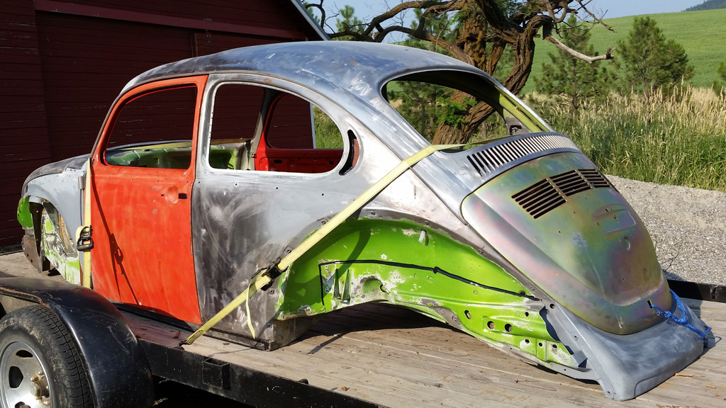
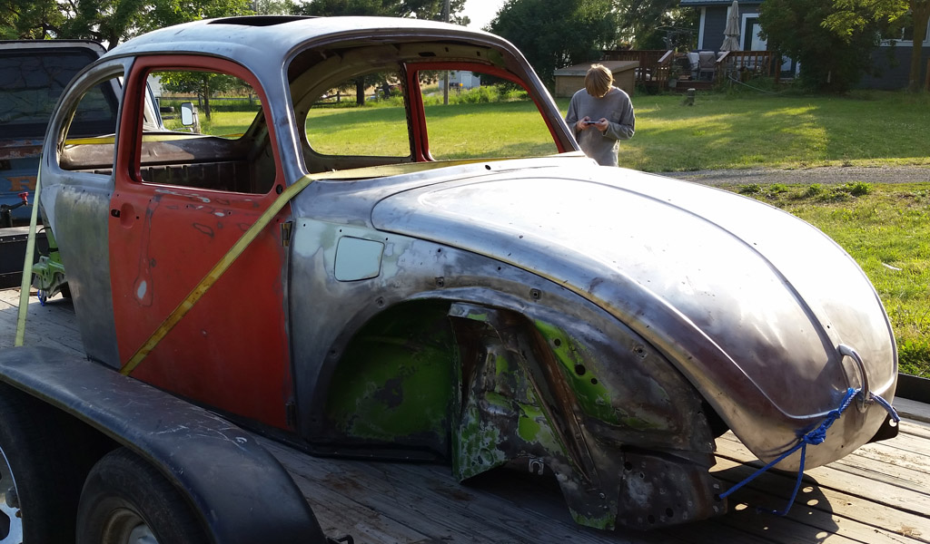
We have a paint shop lined up -- third time is a charm. Since the chassis is painted and the body is not painted, we decided that the best approach would be to take the body to the paint shop and have them paint all the interior surfaces. Next we will install the body to the pan and deliver it back to the paint shop. Then they will do the collision repair to the front of the car, complete the body work, then paint.
Here are some shots of the prep on the body before taking it to paint.
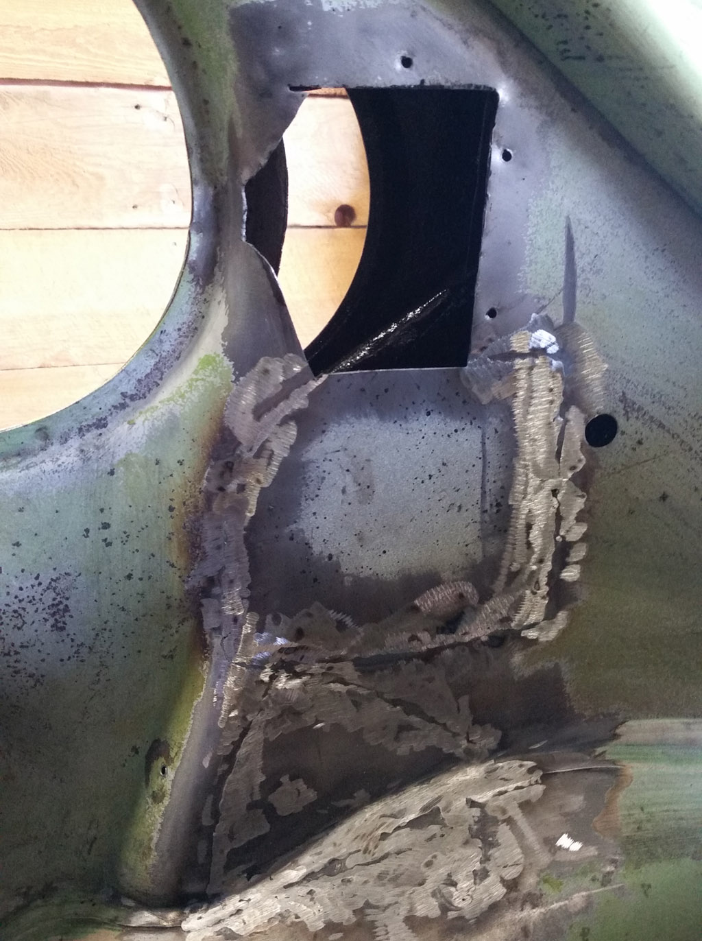
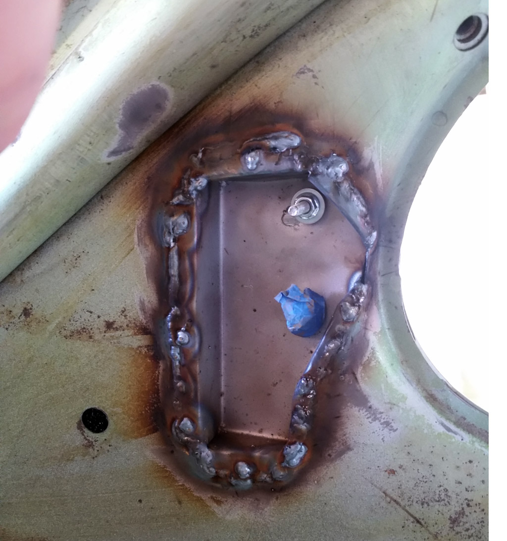
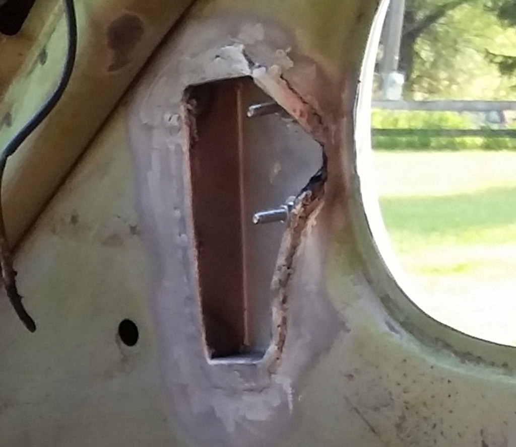
Below the pocket for the passenger-side rear pop-out window actuator, the metal was not rusted all the way through, but it was pretty darn thin, so we added an extra patch below that:
We wanted to coat inside the foam of death area. We got a round brush at the grocery store, and used RustSeal black to coat as best we could inside that area:
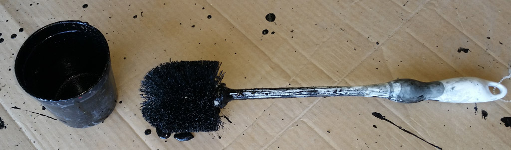
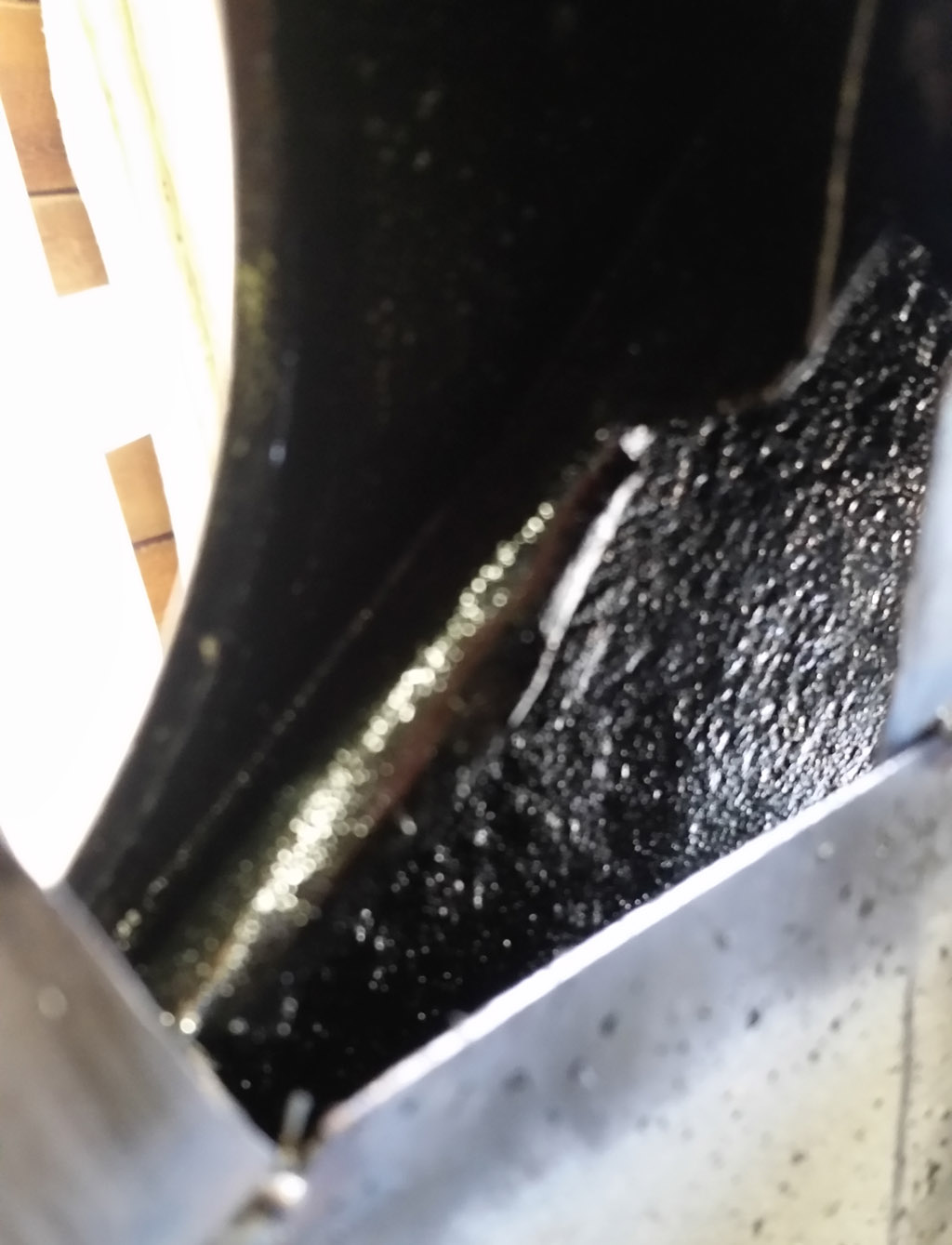
The coverage is pretty good where the brush could reach, and coverage on my face was excellent. We have some RustSeal cavity coater, so we will spray that in the hole after paint is done to try to catch the last places.
We then welded both the rear pop-out window actuator buckets in:
Ground them down, and bead blasted:
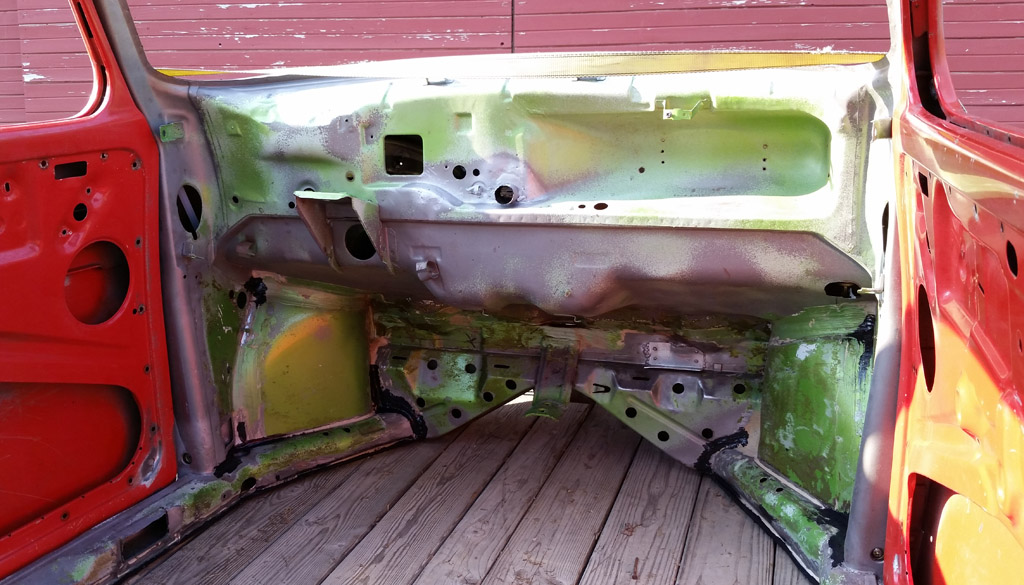
Here is a shot of the interior front, seam-sealed, cleaned and ready for paint:
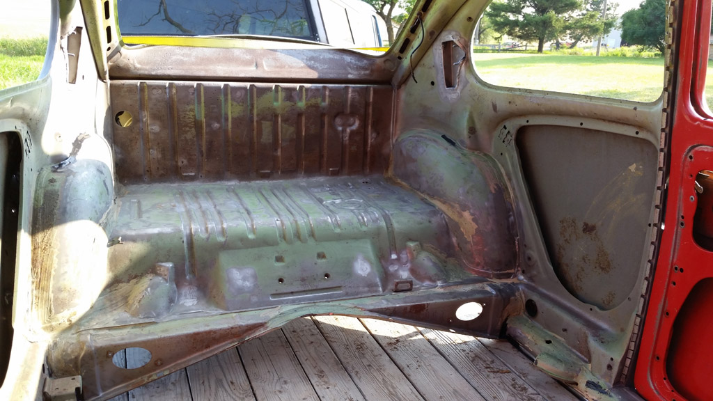
and the rear:
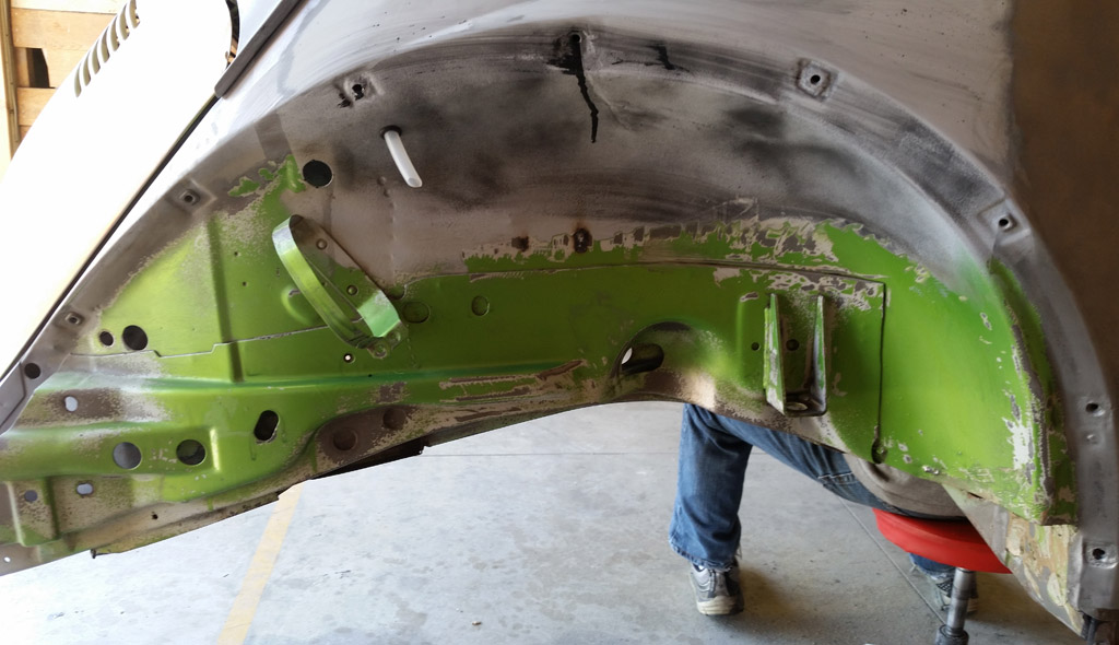
The fender wells had survived quite well, they were undercoated and to a large extent the factory paint was intact, protected by the undercoating. Some time wearing a filter and rubber gloves, using brush cleaner worked in with a chip brush, rag and a small wire brush for the fender wells cleaned up good:
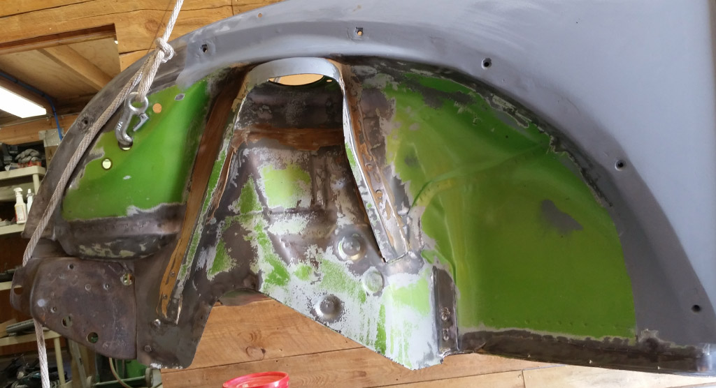
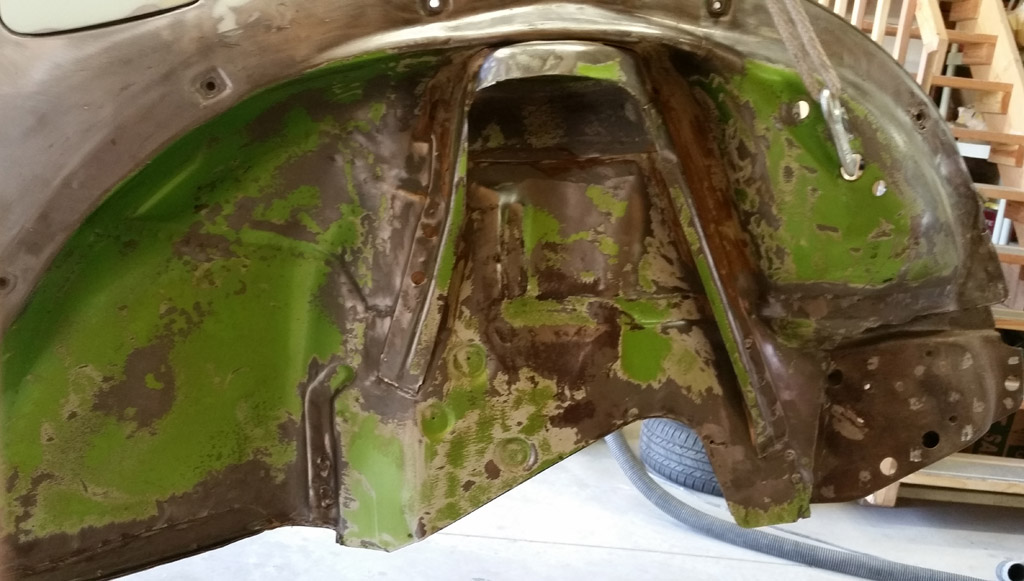
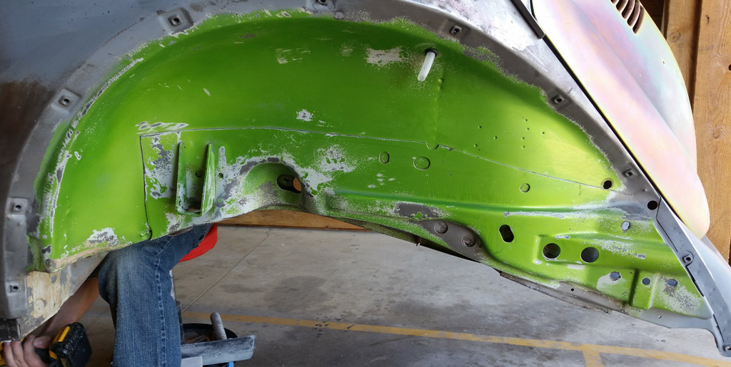
You can see some of the RustSeal paint that we brushed inside has leaked out a fender mounting hole:
Off to the paint shop:
 |
|
| Back to top |
|
|
Baxsie
Joined: 12 Apr 2012
Posts: 253
|
| Posted: Fri Aug 08, 2014 5:24 am Post subject: Engine Tin Painted, Body In Primer |
|
|
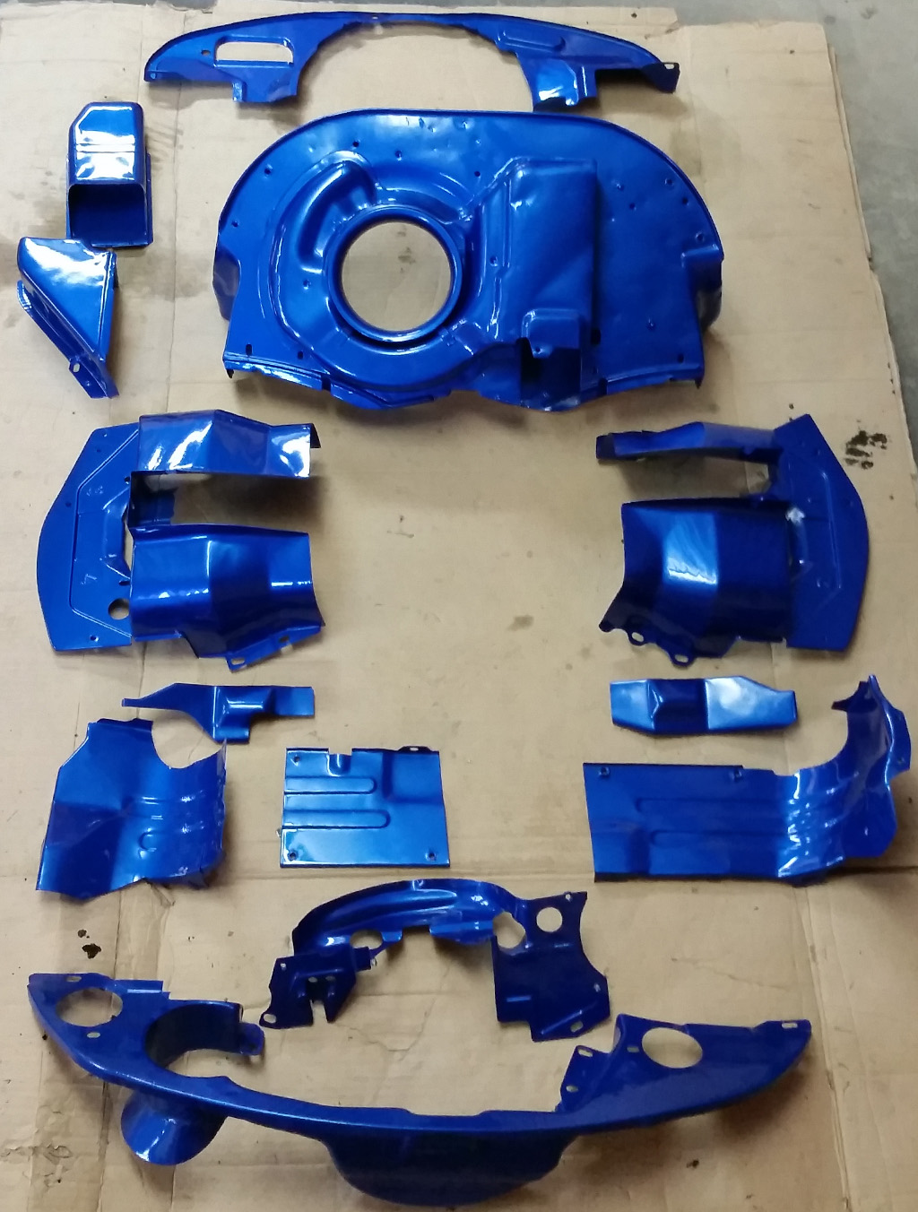
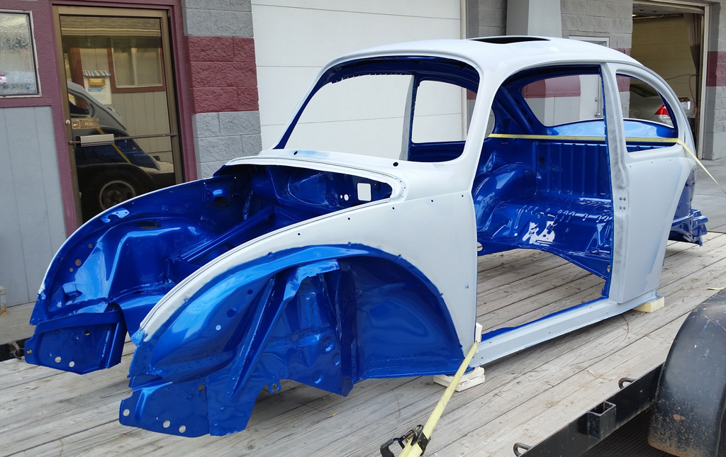
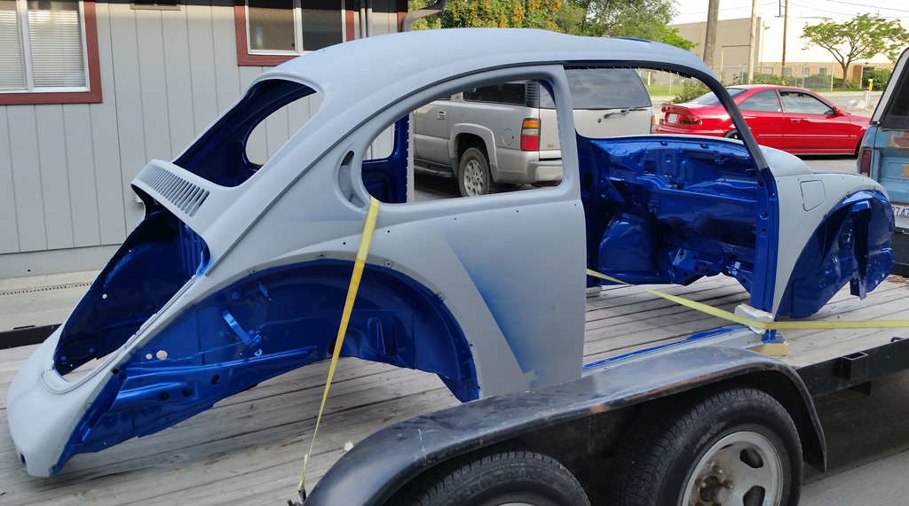
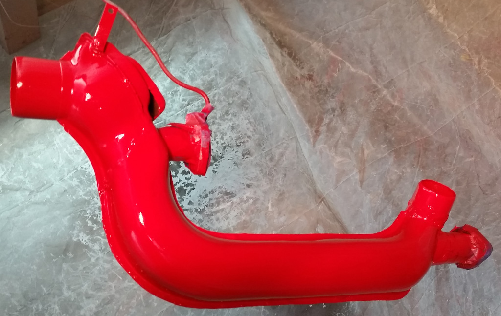
We asked the body shop to shoot the engine tin for us in the body color. It looks very pretty, can't wait to see it assembled:
The body shop has been working on smoothing and straightening the car. Here are some early shots in primer:
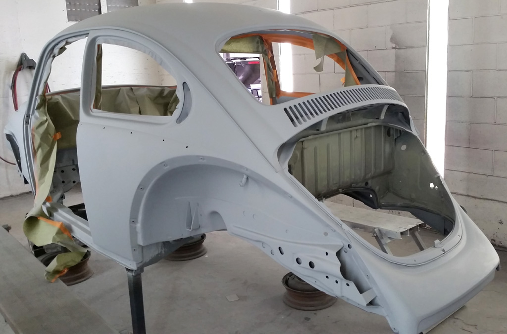
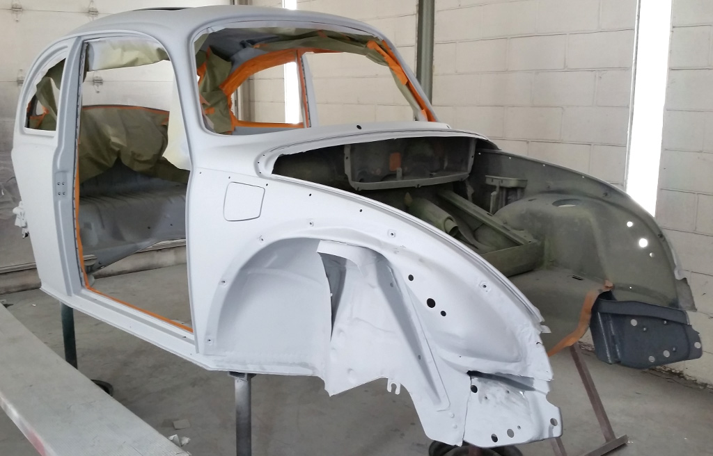
Those guys can do more in a couple of weeks than I can do in a couple of years. |
|
| Back to top |
|
|
Baxsie
Joined: 12 Apr 2012
Posts: 253
|
| Posted: Fri Aug 08, 2014 5:24 am Post subject: Testing Awesome Powdercoat thermostat for an Air-cooled VW |
|
|
Dang, those are some pretty serious suspension mods.
We installed our Awesome Powdercoat "German Style" new thermostat. Here is a video of it operating:
https://www.youtube.com/watch?v=P2qbvfJgPU4 |
|
| Back to top |
|
|
Baxsie
Joined: 12 Apr 2012
Posts: 253
|
| Posted: Fri Aug 08, 2014 6:00 am Post subject: Catching up: Firehose of pictures |
|
|
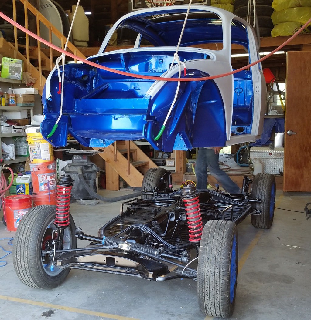
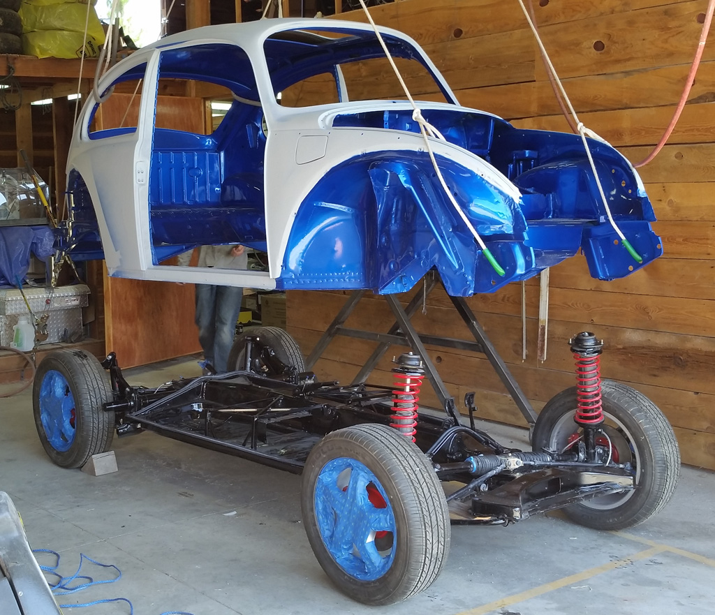
Body back from the paint shop, with the interior and jams painted:
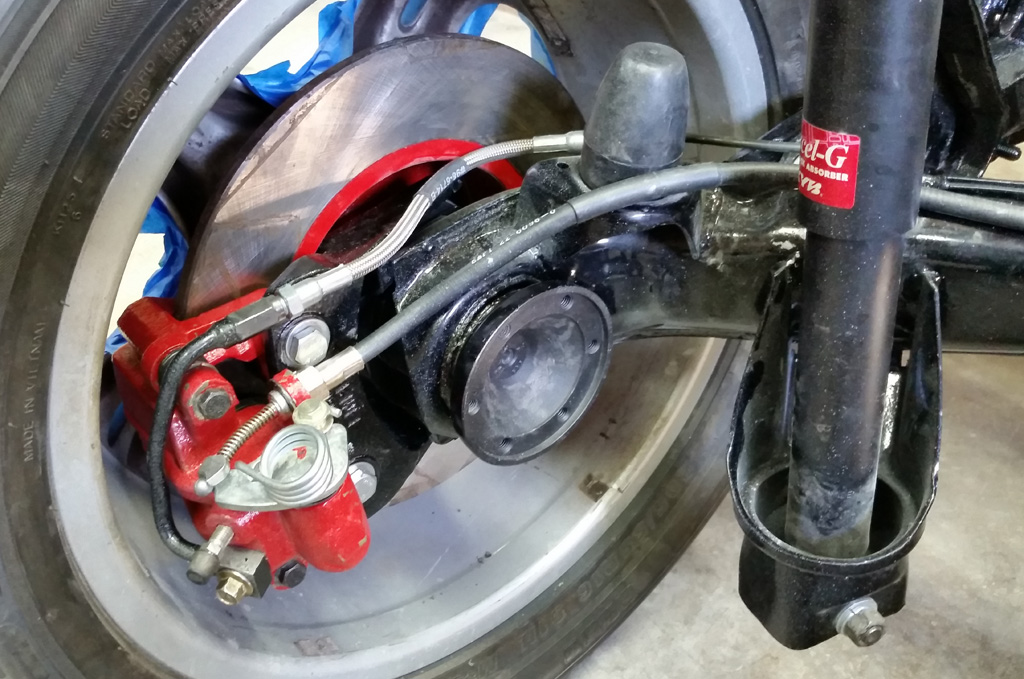
Once we installed the emergency / parking brake handle and cables, we could not adjust it to where the rear disc calipers emergency lever would actuate properly. The cable was too long. Additionally, we would have liked the bowden tubes to be a bit longer so we could curve them at least slightly away from the axel drive shaft. We ended turning a spacer/extender on the lathe that extends the tube by 18mm:
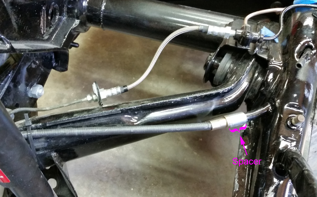
The parking brake bowden tube now routes acceptably:
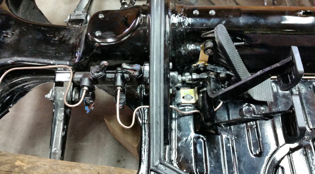
We installed the pedal cluster and master cylinder, as well as new brake lines:
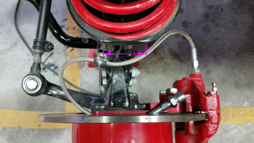
For whatever reason, the struts seemed to be a bit closer to the wheels than we remembered from the first test assembly. We clearanced the strut a bit where it holds the spring, that gives us about 3/16" more room. Still damn close, but better:
Getting ready to lower the body onto the pan / chassis:
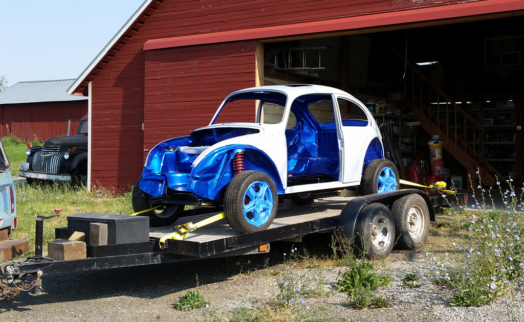
After 3 days of intense hours, we were on our way back to the body shop:
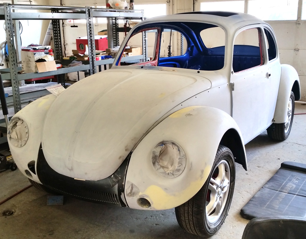
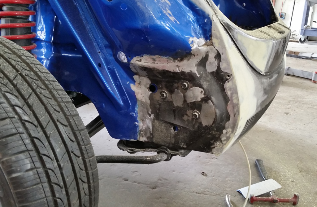
Back at the shop, fenders installed, hood installed, they are getting ready to do the collision repair on the front end:
 |
|
| Back to top |
|
|
project_dog
Joined: 21 Apr 2014
Posts: 33
|
| Posted: Sat Aug 09, 2014 2:34 am Post subject: |
|
|
| Wow. A lot of great work man. congrats. |
|
| Back to top |
|
|
SB1303S
Joined: 13 Aug 2014
Posts: 2
Location: COLOMBIA
|
| Posted: Wed Aug 13, 2014 6:07 am Post subject: What an interest good job!!! |
|
|
Hello I´m writing you from Colombia South America.
I own a Super Beetle 73 1303S and I just been looking all you did with this super 1975 and WOW I just wanted to say Congratulations... And ask for some final pictures, if you have some let me know where to see it...
Also I wanted to ask if maybe you can help me with some information that I need... I saw that you made maintinance to the rack and pinion steering box... right now mine is working badly and when you drive it sounds on the front like having stones in the trunk, but I´ve been trying to find a new one in my country but I haven´t find one and I believe that I won´t find it it is really hard to find. So if you can help me about instructions to repair or what should I check.
Thanks for your time...
Regards..
Luis 
_________________
VW is a family... |
|
| Back to top |
|
|
Baxsie
Joined: 12 Apr 2012
Posts: 253
|
| Posted: Sat Aug 16, 2014 7:46 am Post subject: Aluminum parts Red Anodized |
|
|
Thanks for the kind words, project_dog.
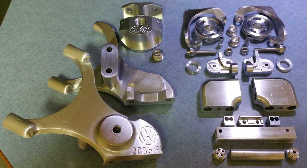
We have a pretty good pile of aluminum parts that did not have surface treatement:
A quick trip to Noavation for red anodizing yeilded this beautiful pile of parts:
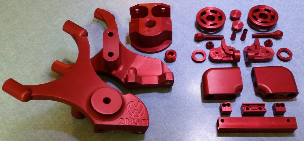
Now it is time to get serious about the final engine assembly  |
|
| Back to top |
|
|
Baxsie
Joined: 12 Apr 2012
Posts: 253
|
| Posted: Sat Aug 16, 2014 7:54 am Post subject: Re: What an interest good job!!! |
|
|
| SB1303S wrote: | | . . . ask for some final pictures . . . |
It is still a work in progress. I will for sure post pics here as we go.
| SB1303S wrote: | | . . . Super Beetle 73 1303S . . . maintenance to the rack and pinion steering . . . |
In my understanding, the rack-and-pinion did not come until 1975. Are you sure you have rack-and-pinion?
Here are the posts where I worked on our rack-and-pinion:
http://www.rcvwclub.org/phpBB2/viewtopic.php?p=9049#9049
Basically is was disassemble, clean, smooth wearing surfaces, grease, reassemble.
You can still get the new boot from CIP1:
http://www2.cip1.com/ProductDetails.asp?ProductCode=C16-133-831 |
|
| Back to top |
|
|
Baxsie
Joined: 12 Apr 2012
Posts: 253
|
| Posted: Sat Aug 16, 2014 8:11 am Post subject: Front collision damage repair |
|
|
Way back in the early stages of this project, we started to do the re-repair of the poorly repaired front end collision damage (ref: http://www.rcvwclub.org/phpBB2/viewtopic.php?p=8976#8976 ). We got to the point of deciding that the work was really beyond our skillz and that we would let the body shop do it.
That day is here.
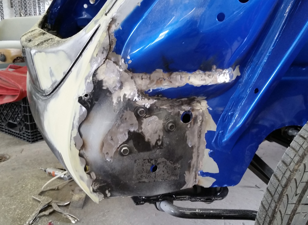
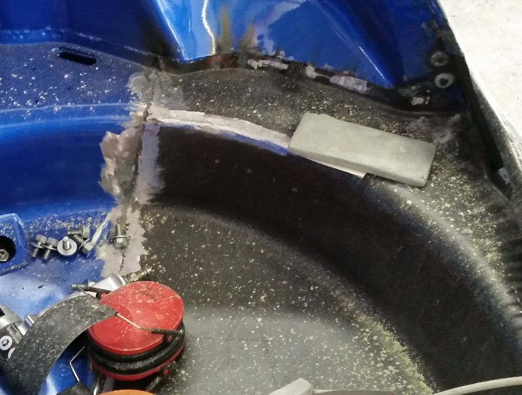
Of course the professional body guys make it look great and easy. |
|
| Back to top |
|
|
Baxsie
Joined: 12 Apr 2012
Posts: 253
|
| Posted: Sun Aug 17, 2014 7:56 am Post subject: Throttle Cable Bracket: Second Try with Pulley |
|
|
A while back, we made some throttle cable brackets that worked with the Sync Link pulleys we have.
On testing, we found that the motorcycle throttle cable tube that we used to make a 90 degree bend in the cable path makes too much friction. It is plastic lined, and we tried cable lube, but there is still a lot of friction in that tube. We think the high force of the IDF return springs are making the cable dig into the plastic liner, where a smaller force would just ride along the top as it is designed.
Additionally, since that design used two of the IDF mounting studs, there is a conflict with the fuel injector manifold hold down clamp on the center stud on one side -- the side we did not test on.
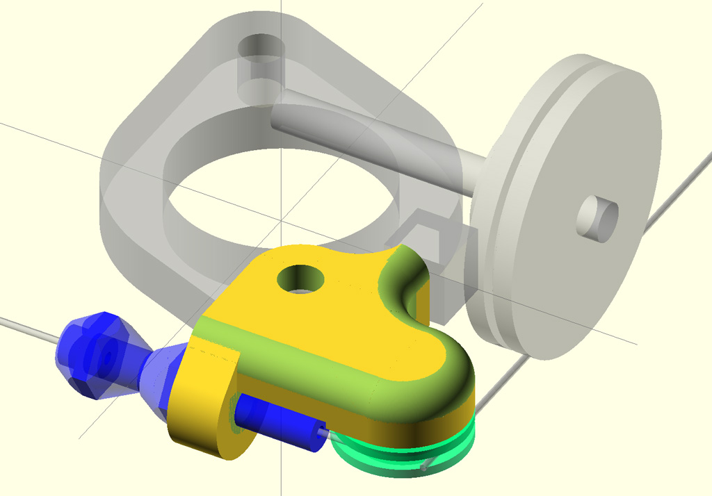
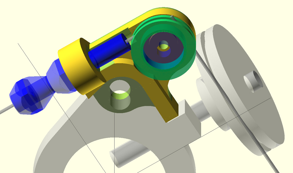
So now we have a new design, that uses a ball-bearing pulley for a near frictionless turn.
We started with the CAD model and FDM 3d prints as usual:
Stuck it on the mill -- getting better at that process:
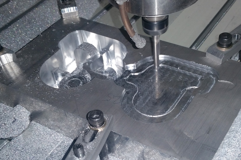
https://www.youtube.com/watch?v=1MktzSPTzJ4
Then gave it a test on the bench:
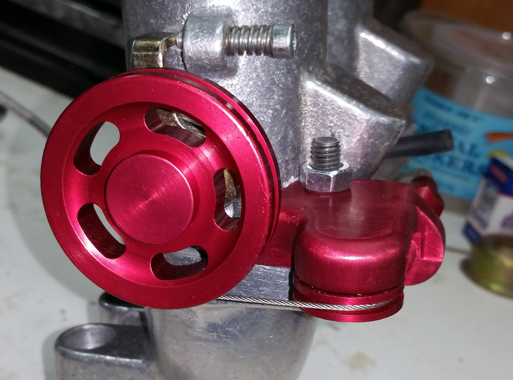
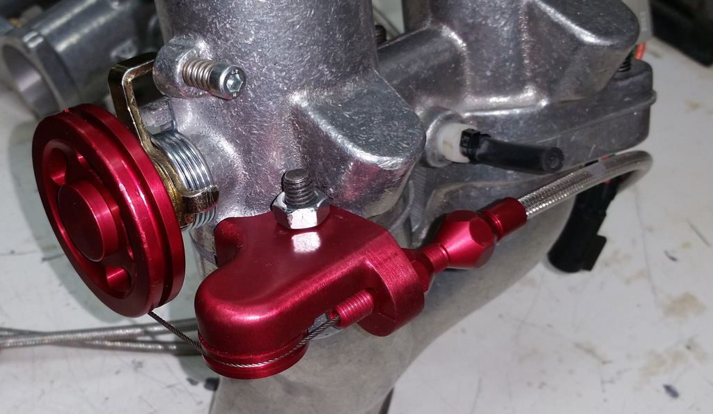
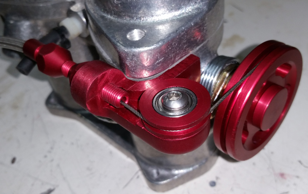
The action is much better. The force to actuate (both) throttles looks to be about two times the force needed to operate a stock carb. We have a lined throttle cable from the pedal to the splitter, so I guess we will have to cross our fingers that the increased force will not lead to short throttle cable life.
The cable adjuster and stop nut are from a Lokar throttle cable kit. |
|
| Back to top |
|
|
Baxsie
Joined: 12 Apr 2012
Posts: 253
|
| Posted: Sun Aug 17, 2014 8:07 pm Post subject: Installing Megasquirt CHT sensor in factory VW location |
|
|
Mario from The Dub Shop included a CHT sensor as part of the MS3 Pro package. Typically he installs it under a tin screw that is threaded into the head.
Well, with the FI tin and a head that has a boss on it for mounting a factory CHT sensor, I just had to put the sensor at the factory location.
Drilling and blind tapping a M6x1 hole into the cylinder head had some pucker factor going on, but as far as I can tell I did not drill into the combustion chamber
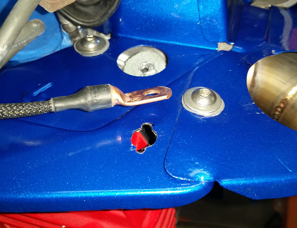
Here is a shot of the boss drilled and tapped (and prepared with anti-seize). The keyhole shaped opening in the tin is to let the sensor pass through with a minimal size hole:
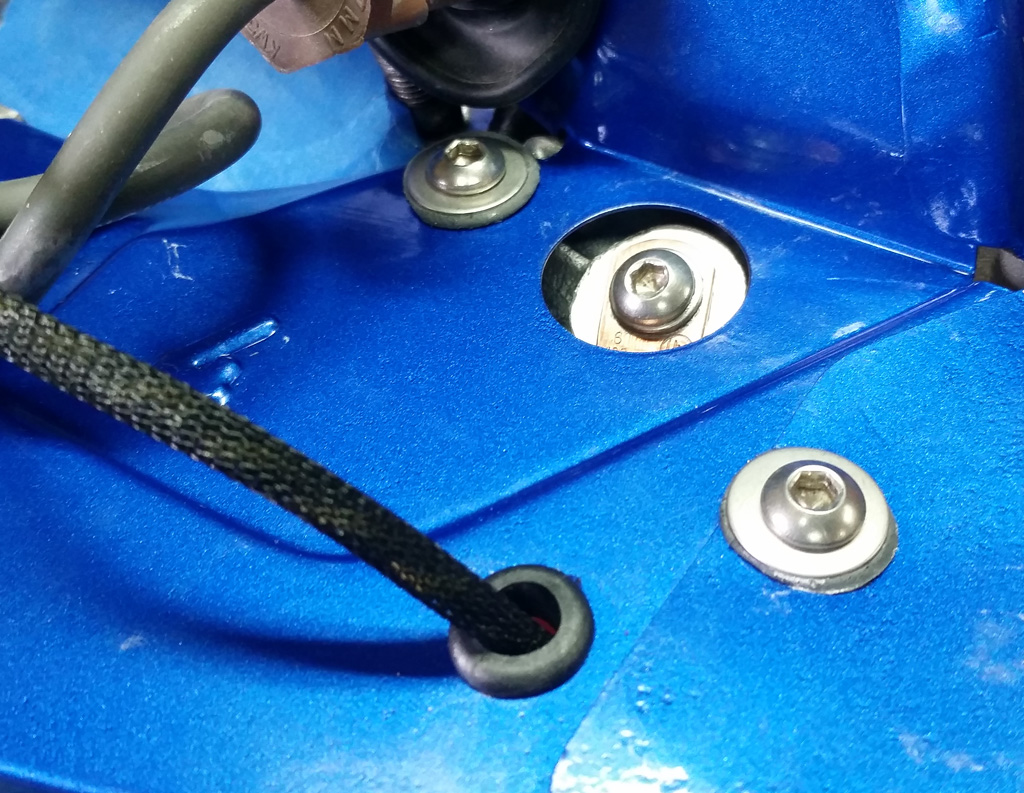
The sensor is attached to the head one of the stainless steel button head screws we are using for the tin. A standard grommet cleans up the hole:
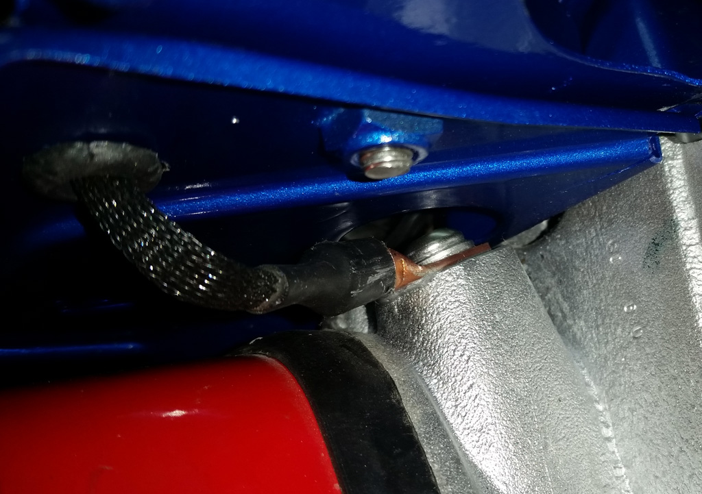
Under the tin looks reasonably clean:
 |
|
| Back to top |
|
|
Baxsie
Joined: 12 Apr 2012
Posts: 253
|
| Posted: Sun Aug 31, 2014 9:48 am Post subject: Stainless Steel Heat Exchanger: Performance and Comfort |
|
|
Starting way back (see: Getting naked with a heat exchanger), we have been trying to find a way around the heat (OG heat exchanger) or performance (big J tube) trade-off.
I think we have it.
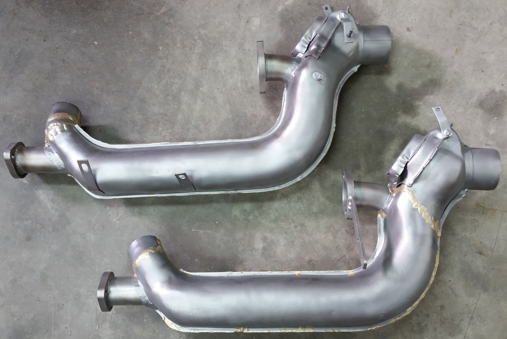
We started with a quality heat exchanger from WolfsBurg West, and the semi-custom stainless steel flanged J tube that was supplied as part of our A1 exhaust.
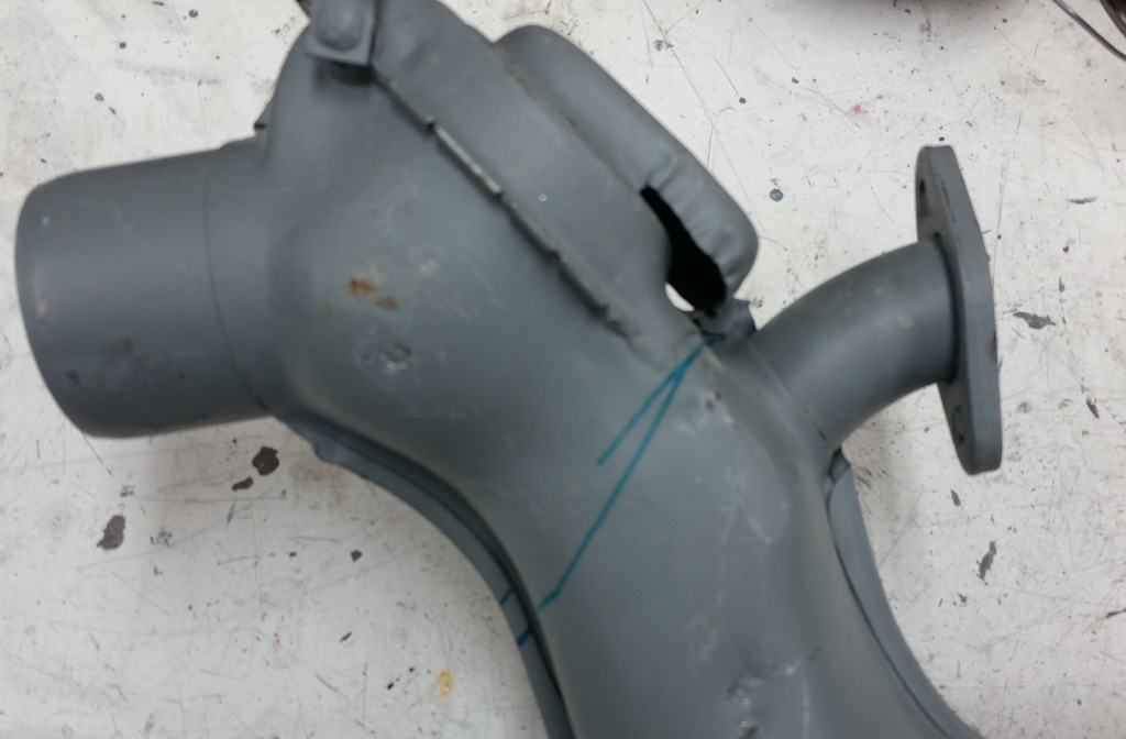
From experimentation, we knew exactly where we wanted to cut to be able to get the old core out, and the new j-tube in:
We removed the factory folded seam by using the angle grinder:
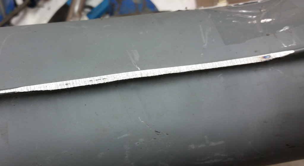
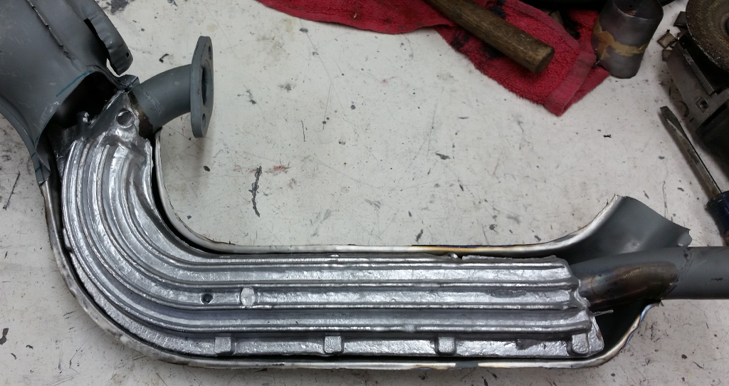
Then peeling away the strip:
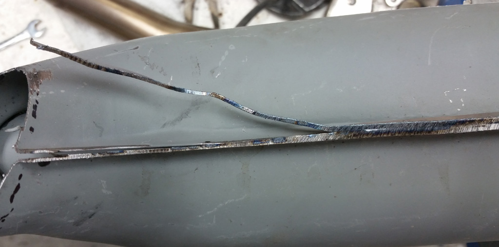
This exposes the core of the reproduction / repop heat exchanger. To their credit, there is the nice aluminum pour around the j-tube, but the finning is much less agressive than the factory, and the exhaust pipe is not convoluted:
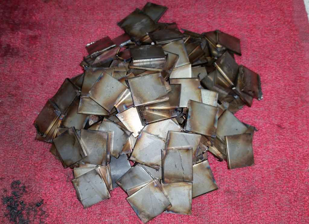
A local sheet metal shop cut us 3/4" wide strips of 14 gauge sttainless sheet, which we then cut down to 3/4" squares using the chop saw:
Next came the ardous task of attatching the stainless-steel fins to the stainless steel J-Tube. Originally we attempted using the TIG. My TIG welds were horrible. My son made much nicer welds-quite beautiful, in fact, but the TIG welding process was brutally slow. After asking around, we found some 0.030 308 stainless MIG wire and a special gas that allows using the MIG to weld stainless. This made the process go much faster, although the welds are not quite as slick as my son's TIG welds:
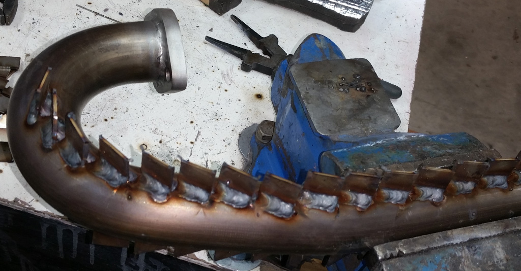
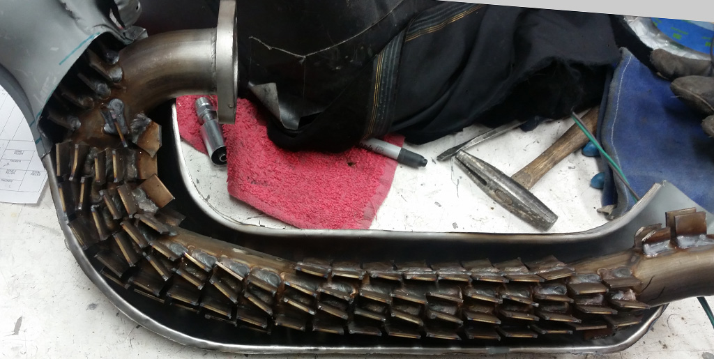
Here is a picture of all the tabs welded on. There is an an equal number on the back side:
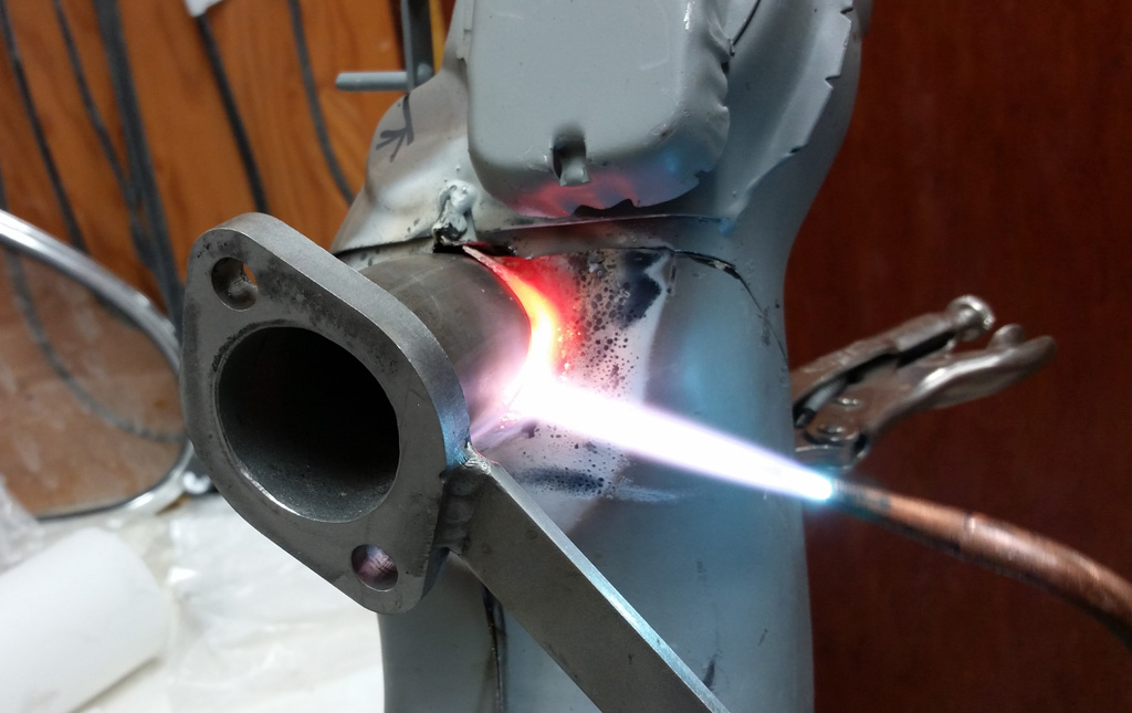
We used the torch and pliers to make the openinf in the skin bigger, and shape it around the J-Tube:
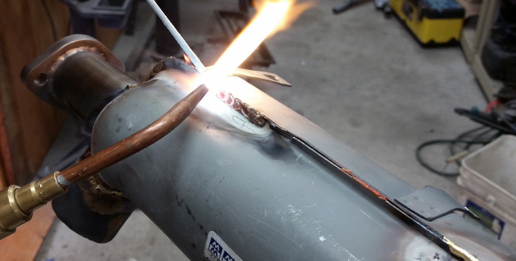
My son then brazed the skin closed again:
A quick bead blast:
We still had some Rust-Seal Motor Coater, so we prepped it with the Rust Blast etch and then shot it:
Hopefully that will give some decent heat this winter! |
|
| Back to top |
|
|
Baxsie
Joined: 12 Apr 2012
Posts: 253
|
| Posted: Sun Aug 31, 2014 8:18 pm Post subject: Engine Assembled with Tin Painted |
|
|
Got the heat exchangers assembled to the engine, most of the accessories connected:
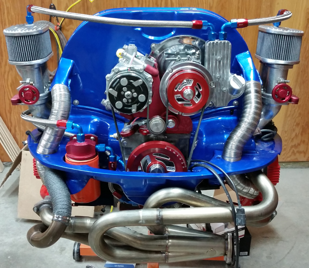
Manifolds will have to come out for engine install, so they are still loose. |
|
| Back to top |
|
|
|
|
You cannot post new topics in this forum
You cannot reply to topics in this forum
You cannot edit your posts in this forum
You cannot delete your posts in this forum
You cannot vote in polls in this forum
You cannot attach files in this forum
You can download files in this forum
|
|