| View previous topic :: View next topic |
| Author |
Message |
Baxsie
Joined: 12 Apr 2012
Posts: 253
|
 Posted: Sun Dec 16, 2012 8:16 pm Post subject: Posted: Sun Dec 16, 2012 8:16 pm Post subject: |
 |
|
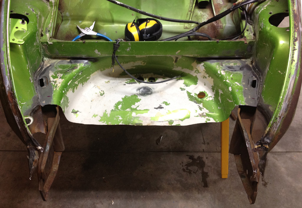
We made some progress on replacing the spare tire well. The heavy bumper supports were munged around a bit. We carefully adjusted them with big blue (8lb hammer) until the cross measurements were the same.
In this shot, we have removed the front ~ 1/2 of the spare tire well:
Here is a test fit of the rough-trimmed new Wolfsburg West Spare Tire Well in place:
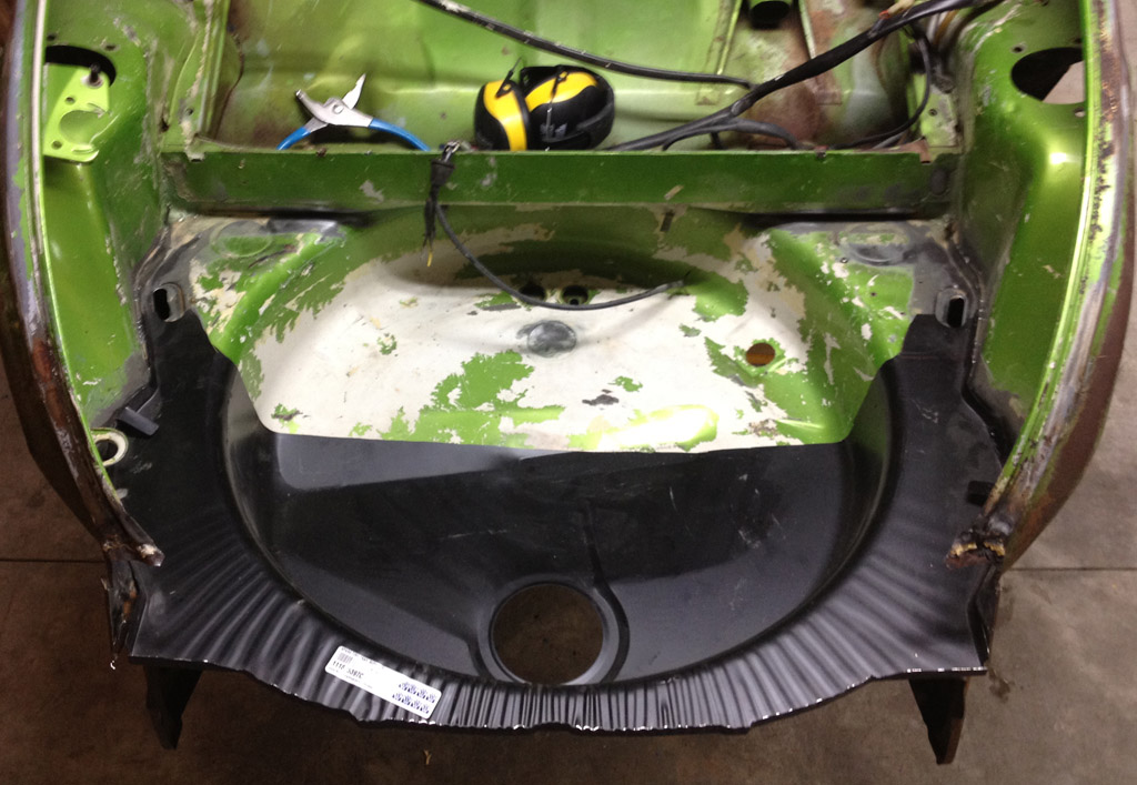
Quite encouraging actually. It seems to be a great fit. Much more trimming and fiddling to do. I plan to make some small holes and use sheet metal screws to assure that all the parts are straight and line up with each other before doing any welding. I will assume that the new sheet metal is straight, and that may make it necessary to fudge the bumper supports a bit to line them up.
I went ahead and ordered new fenders from CIP1. I decided the worry of the old fenders either not matching, cheaper construction than the modern CIP ones. I _know_ that all the old ones need various levels of body work, and I only _suspect_ that one is OG.
In what may make purists choke, we decided to add an early Wolfsburg crest and early VW emblem to the hood. Since we need a wide (old style) trim piece to match up with the Wolfsburg crest, we decided to use the early style trim (in stainless) for the entire car. A side benefit of going to the wider trim is that it will be easier to hide where this car was "de-chromed".
I also got some new tail lights, new lenses for the front turn signals, and some LED pucks to place in the new lights.
I decided to try one of these "Mexi Hood Seals":
http://vwparts.aircooled.net/Front-Hood-Seal-Beetle-and-Superbeetle-Mexibug-p/mexihoodseal.htm

I'm on the fence about if that will work well.
Last edited by Baxsie on Fri Aug 08, 2014 12:24 pm; edited 1 time in total |
|
| Back to top |
|
 |
Baxsie
Joined: 12 Apr 2012
Posts: 253
|
| Posted: Wed Dec 19, 2012 11:11 am Post subject: |
|
|
Got the first batch of parts back from plating. Here is a small sample:

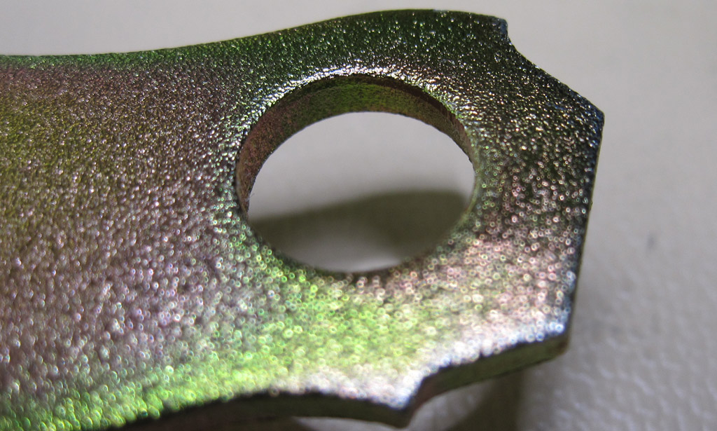

The texture is from the bead blasting. More photos later.
Novation, Inc.
2616 N. Locust Rd, Spokane, WA 99206
http://www.novationinc.net/
Last edited by Baxsie on Fri Aug 08, 2014 12:24 pm; edited 1 time in total |
|
| Back to top |
|
|
Baxsie
Joined: 12 Apr 2012
Posts: 253
|
| Posted: Fri Dec 21, 2012 9:01 pm Post subject: |
|
|
I keep finding things out that I did not know. I was very surprised to find a beefy side-impact beam in the door:


I do not remember a beam like that on my 1972 1302 Super. When were those added?
Last edited by Baxsie on Fri Aug 08, 2014 12:25 pm; edited 1 time in total |
|
| Back to top |
|
|
Baxsie
Joined: 12 Apr 2012
Posts: 253
|
| Posted: Thu Jan 03, 2013 10:19 pm Post subject: |
|
|
OK, back to the front-end collision repair.
There are many parts that have been removed up there. We need to find something that is in the "right" place, so we can base the other parts positions of that. Right now there are not too many parts that agree with each other about where they should be.
The 1975 has a thick, massive bumper brace that we think is not damaged, other than a little side-to-side action, which we think we have made fairly straight now.
That brace is originally welded to the wheelhouse. The replacement wheelhouse section has holes in it for the '73 style bumper mounting, but not the '75 style. Interestingly, the original wheelhouse has holes for the older style and the newer style.
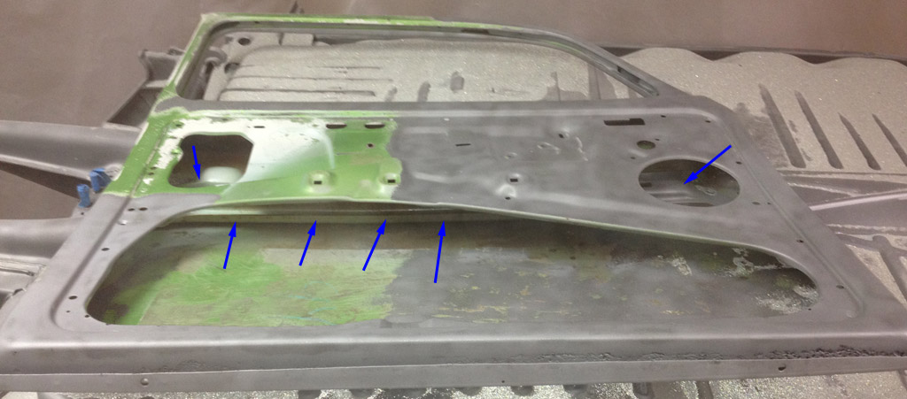
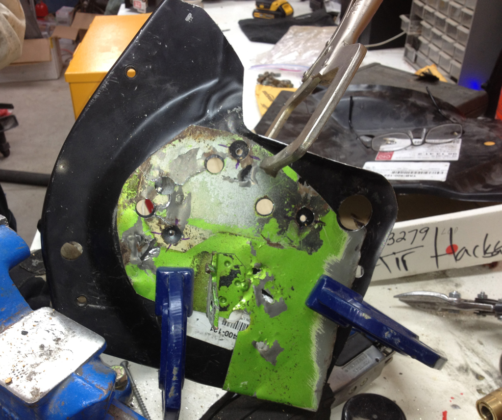
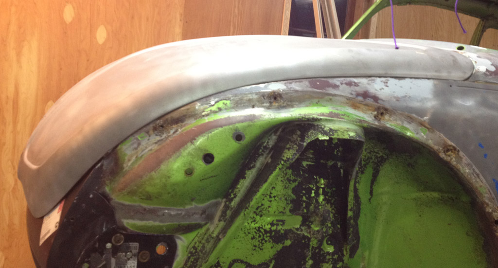
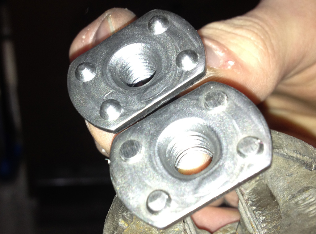
In this picture, we have flattened out the old wheelhouse section (green), and are using it a template to drill the '75 style holes in the repair wheelhouse section (black).
Of course the holes do not line up exactly, but we tried our best to center them as well as possible:
We then used the '75 bumper mounting holes to position the new wheelhouse section (black) on the heavy bumper mounting brace, tweaking it as well as we could based on the new holes we just drilled and the '73 style holes which conveniently had masked perfect dots of paint from the original wheelhouse. Now that this replacement wheelhouse repair section is in place (but bolted only, not welded yet), we plan to use it as the "base point" for the rest of the work.
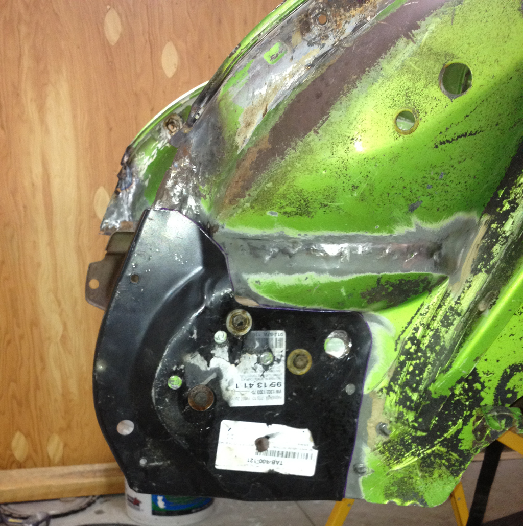
The flip side, just for reference:

The next step will be to repeat this process on the passenger side. Then we will test assemble the fenders, spare tire tray, front apron, and maybe even the hood based on the careful placement of these parts.
I am open to advice on better ways to do this. I am kind of making it up as I go along.
Last edited by Baxsie on Fri Aug 08, 2014 12:25 pm; edited 1 time in total |
|
| Back to top |
|
|
Baxsie
Joined: 12 Apr 2012
Posts: 253
|
|
| Back to top |
|
|
Baxsie
Joined: 12 Apr 2012
Posts: 253
|
| Posted: Sat Jan 12, 2013 10:33 pm Post subject: |
|
|
I have been trying to reconcile the "heat or performance" conundrum. I decided to look deep inside a heat exchanger to see what I'm up against. Luckily Troy had an old OG exchanger to put on the slab for science.
The first cut won't hurt at all:
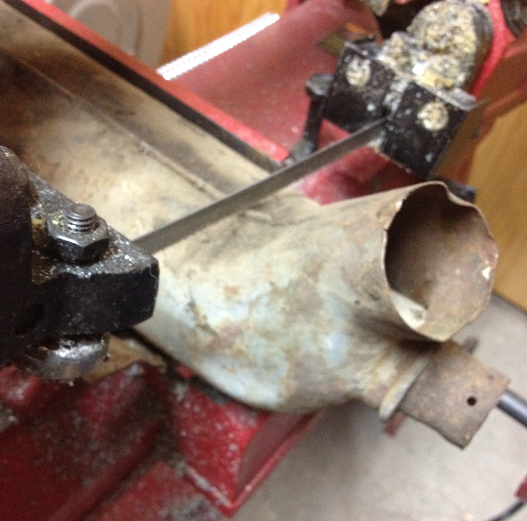
I made a total of 4 cuts:
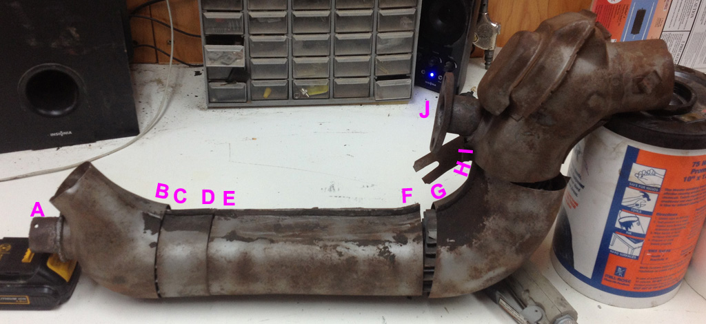
Here are the insides:
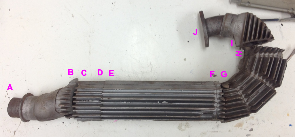
Here are the shots of the cross sections corresponding to each letter:

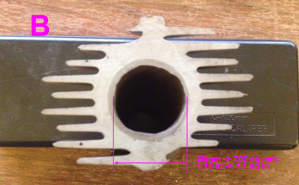

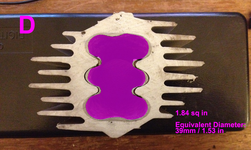
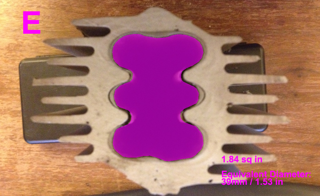
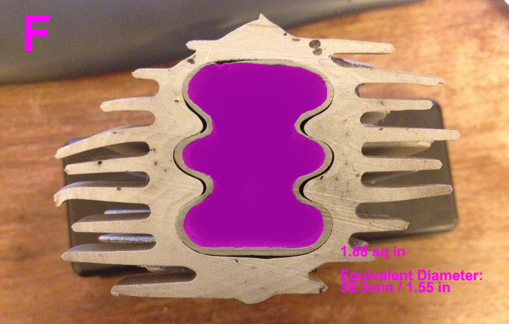
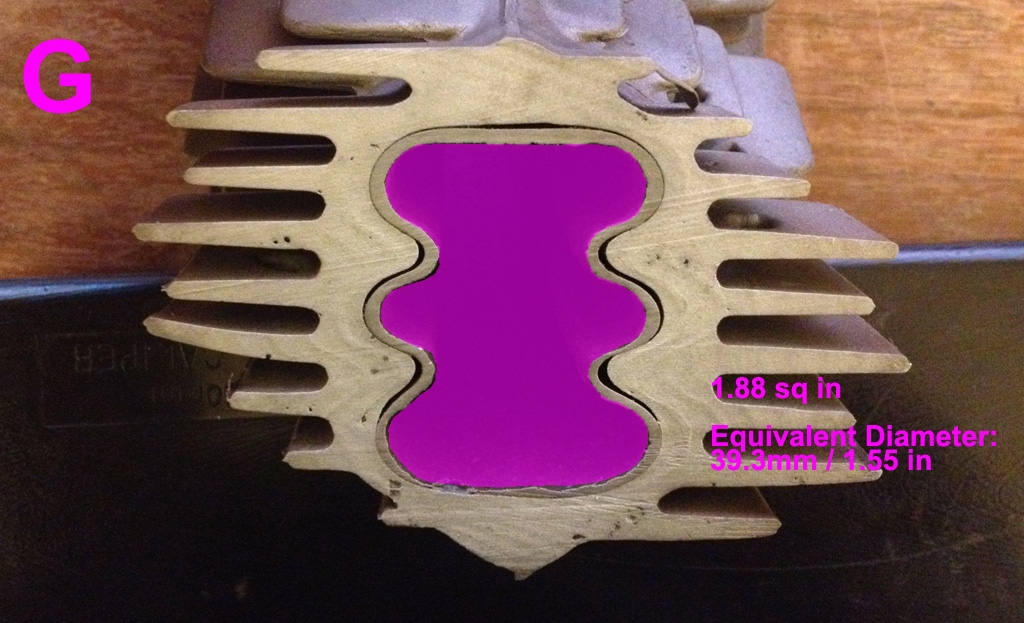
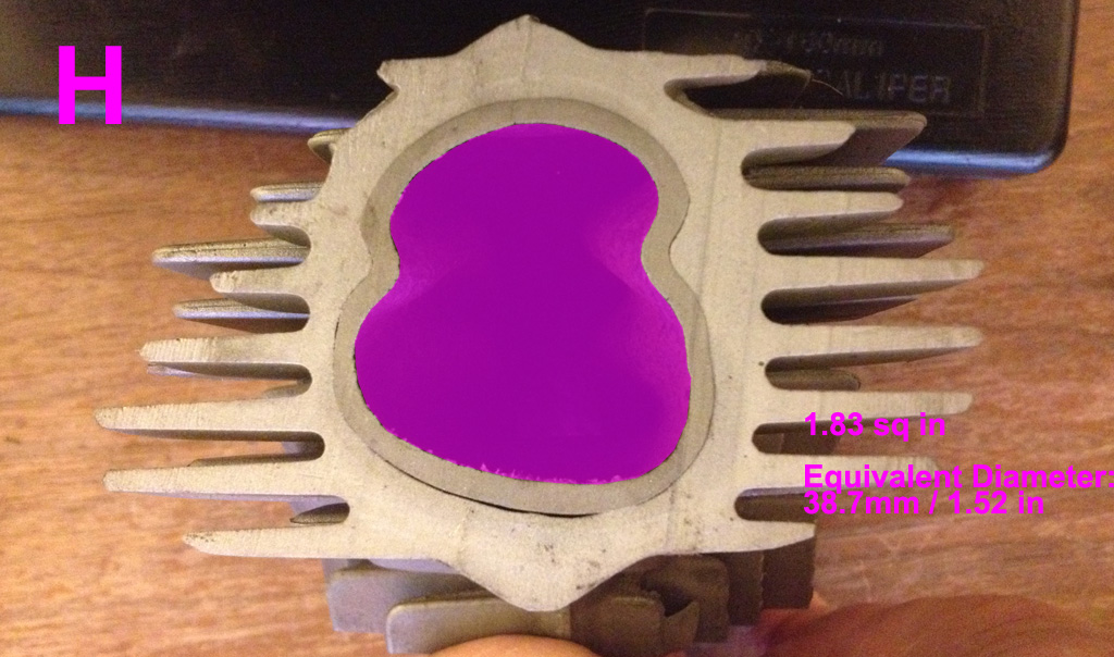
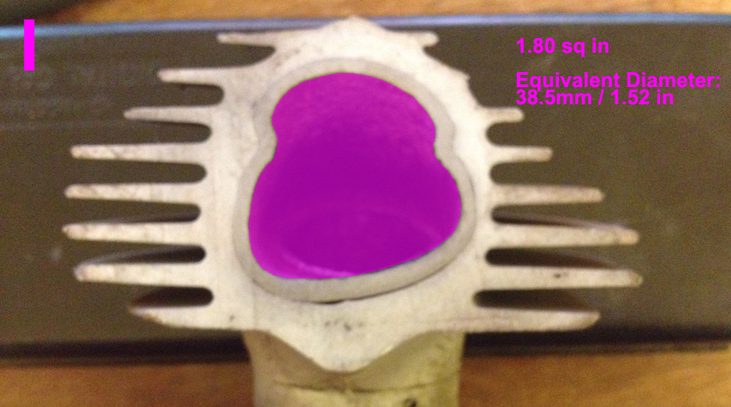
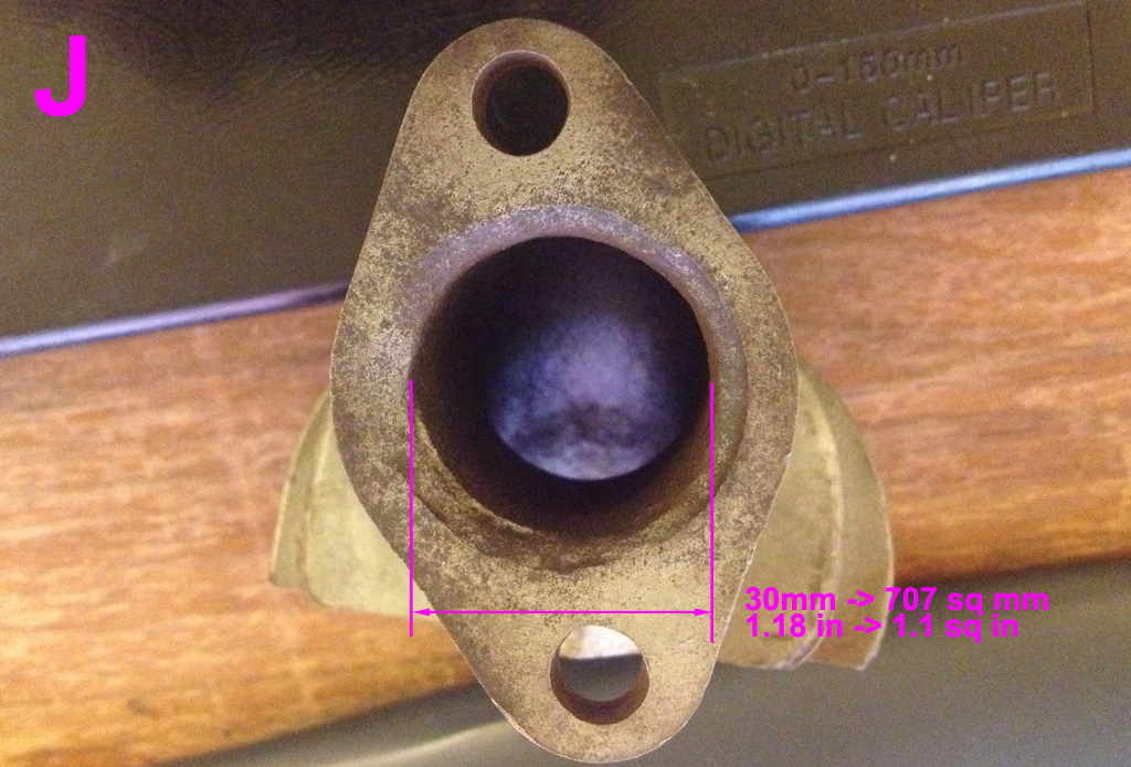
I measured the cross sectional area by scaling the photo, outlining the area, asking photoshop to count the pixels then converting back into area.
So all the restriction happens from A through D, and I to J. That is to say the cross-sectional area in from E-H is equivalent to a 1.5" ID tube. There would be more friction since the inside of the convoluted OG tube has more surface area.
The C-D transition is very smooth and nice:

There is another transition in the I-J section (right by the head) that is pretty ugly:
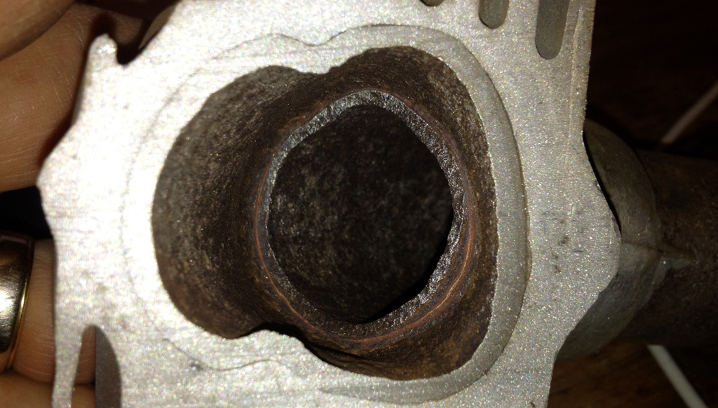
Also interesting is how this heat exchanger has corroded through the steel and into the aluminum. I do not think there would be a way to detect that outside of cutting or fishing a camera into the heat exchanger. (angled photo looking into E):

There are also several places where the steel and aluminum have delaminated, that is particularly nasty in the F cross section.
Still no answers, but at least I know what I'm up against now.
Last edited by Baxsie on Fri Aug 08, 2014 12:26 pm; edited 2 times in total |
|
| Back to top |
|
|
ONEBADBUG

Joined: 25 Oct 2003
Posts: 440
Location: Spokane
|
| Posted: Sun Jan 13, 2013 8:16 am Post subject: |
|
|
| So, new (real) heater boxes aren't available anywhere? |
|
| Back to top |
|
|
Troy Hobbs

Joined: 05 Aug 2003
Posts: 766
|
| Posted: Sun Jan 13, 2013 2:45 pm Post subject: 1974 Super Beetle Project |
|
|
You should edit the title to 75 Beetle. New HD heater boxes with fins are available, but Brent is trying to build some larger diameter pipe heater boxes with heat sinks too. Since his engine size is too large for stock size exhaust and heater boxes.
_________________
TROY
current RCVW club Pres
ARR #3 |
|
| Back to top |
|
|
Baxsie
Joined: 12 Apr 2012
Posts: 253
|
| Posted: Wed Jan 16, 2013 6:03 pm Post subject: |
|
|
HEAT EXCHANGER:
The only solution I can think of at this point would be to make an extruded aluminum fin set that bolts over the straight section of a high performance, large diameter J tube (the E<->F area), and largely fills the outer heat exchanger tin very much like the standard aluminum would.
Requires more thinking.
COLLISION REPAIR:
OK, back to the front end damage. I took the good advice of installing the hood. I am glad I did. Since I sandblasted and made wavy the hood from the white '75, we got the hood of the red '73 parts car. Surprise! It has the "75" bump under the handle, so I assume it is a replacement. Nice. It is not as straight as the white '75 hood was before blasting, but is probably straighter than the white '75 hood after blasting 
We used sheet metal screws to temporarily secure the apron to the front wheelhouse repair sections. We had aligned the front wheelhouse repair sections based on transferring the hole pattern from the original metal to the new section (detailed a couple posts above).
We lined up the hood at the hinge on the driver side:
and on the passenger side:

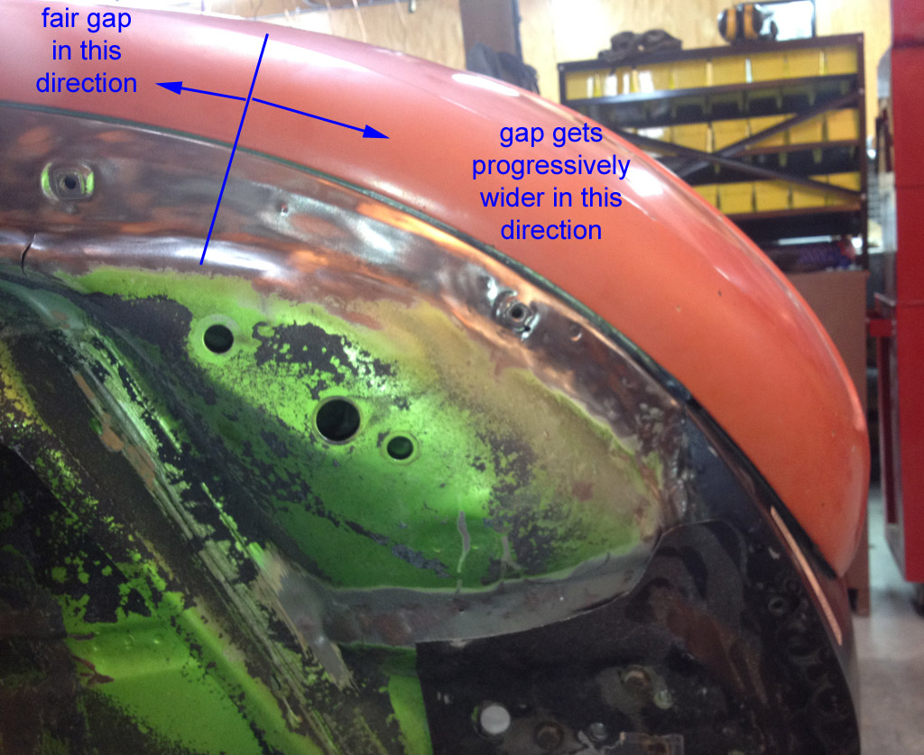
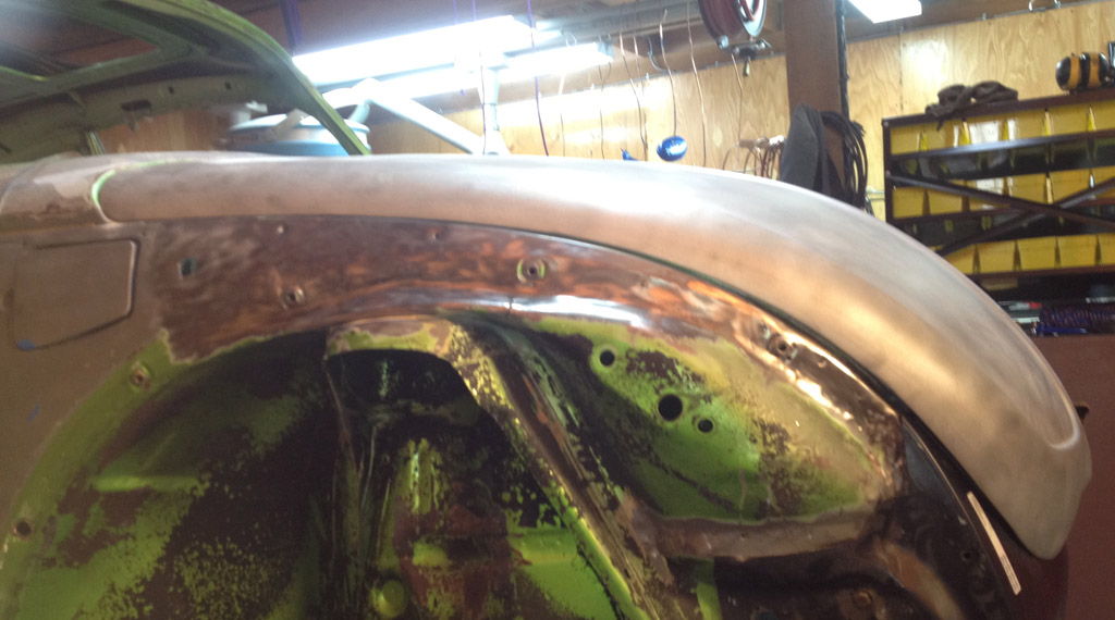
The body under the hood on the driver side lined up nicely:
On the passenger side, the body alignment gets progressively worse:
We measured and checked angles and decided that only the light weight body above the heavy bumper mount was messed up. We made a tool so we could beat on it without making dents:

After a couple of serious thumps with the hammer it came in nicely:

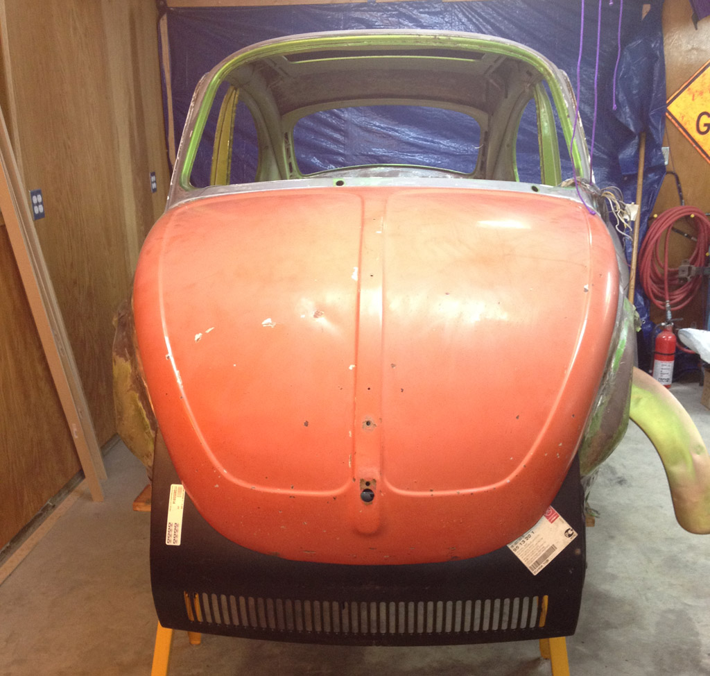
At this point, side-to-side from the front looks pretty good:
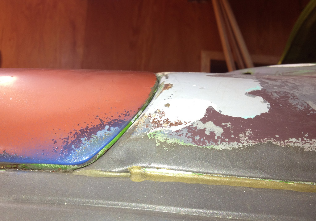
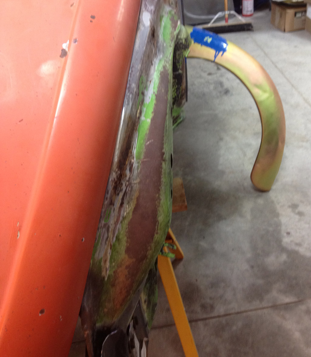
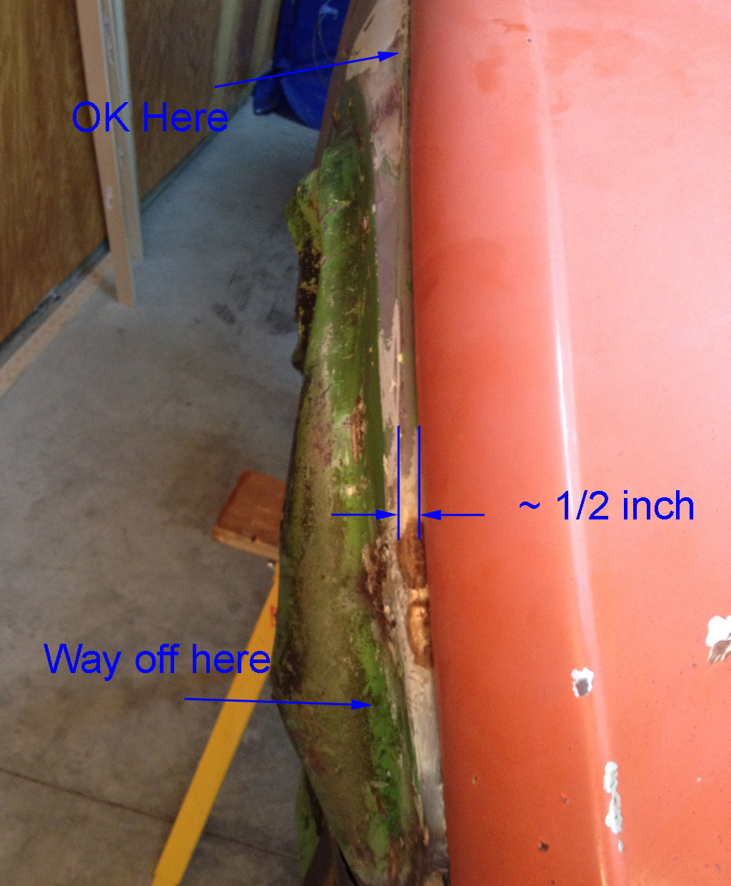
But from the side, there is trouble (the very front-bottom of the hood is touching the apron):
Not quite so bad on the driver's side, but still not good (the very front-bottom of the hood is touching the apron):

We thought that maybe the red hood was bungled, so we tried the white hood, with similar results. It is hard to see, but the very nose of the hood is touching the apron:
How the heck do we fix that?
All I can think of is to move the apron and the "wheelhouse repair panels" towards the rear of the car by 1/4" to 1/2". I thought we had been very careful getting those in the "right" spot. I an very confused if we are off by 1/2".
Ideas?
Last edited by Baxsie on Fri Aug 08, 2014 12:26 pm; edited 1 time in total |
|
| Back to top |
|
|
Baxsie
Joined: 12 Apr 2012
Posts: 253
|
| Posted: Sat Jan 19, 2013 8:41 am Post subject: Re: 1974 Super Beetle Project |
|
|
| Troy Hobbs wrote: | | You should edit the title to 75 Beetle. |
I do not see how to do that. You might have to to do it as administrator.
"1975 LaGrande Super Beetle Rebuild" |
|
| Back to top |
|
|
Baxsie
Joined: 12 Apr 2012
Posts: 253
|
| Posted: Sat Jan 19, 2013 8:52 am Post subject: |
|
|
My original idea was to take section E<-->F, and make adapters for each end that would weld between the ends of a high-performance 1 5/8 J-Tube and the metal lining of the E<-->F heat exchanger section. After seeing how the inside of the heat exchanger is all corroded, I have given up on that idea. Even with a section cut out of a new heat exchanger, making the adapter and welding it in with a perfect seal would be a challenge.
I ordered the 1 5/8 SS sidewinder from A1. He is going to ship SS J-Tubes and opened-but-not-re-welded-closed heater box skins. The idea is that I can try to weld SS tabs onto the outside of the SS J-Tube, or if I get really ambitious, I'll try to come up with some kind of bolt-on aluminum heat sink that clamps around the J-tube in the constant-cross-section E<-->F area, which fills the skin similar to how the stock heat exchanger fills the skin.
For heat, this would be better than a J-Tube, though not as good as stock.
For performance, it would be identical to a high-performance J tube.
It looks like tooling and extruding a small batch (300 lbs to 500 lbs)of heat sinks would be between $2000 and $3000.
I would have to sell a lot of those to pay off that tooling 
The real suck part is that there would not be a way to take a stock heat exchanger, a new J-Tube and my heat sink and make them work. Tiger says the heat exchanger skin cannot be removed from a stock heat exchanger without ruining it. |
|
| Back to top |
|
|
Baxsie
Joined: 12 Apr 2012
Posts: 253
|
| Posted: Sat Jan 19, 2013 7:01 pm Post subject: 1975 Super Beetle Rack and Pinion Steering Assembly |
|
|
Some time ago I disassembled the rack-and-pinion. The boot was cracked two places and you could see some rust in there. If it wasn't for the rust I was sorely tempted to re-grease it and just slide the new boot on.
But once we got it apart I am glad we tore into it.
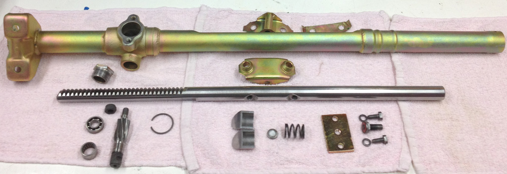
Here are the parts cleaned up:
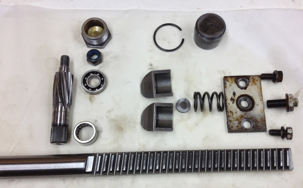
There is some wear:

The original machining marks on the rack are crosswise (marked by small blue double head arrows). Where it is worn the marks are along the rack (larger orange double head arrow).
The tension things are also worn pretty badly. My first reaction would be to get a new, clean large flat file and dress those surfaces.
There was some really-hard-grease or really-decomposed-rubber that had a kind of pink granular texture. Reminded me a bit of a ruined Pink Pearl eraser. That makes me wonder if I am missing a part in there somewhere.
On a cozy night at the homestead with blowing and snow outside, I took the opportunity to cuddle up with a flat file, fine grit wet-or-dry sandpaper, a piece of hardware glass, and the scored rack-and-pinion parts:
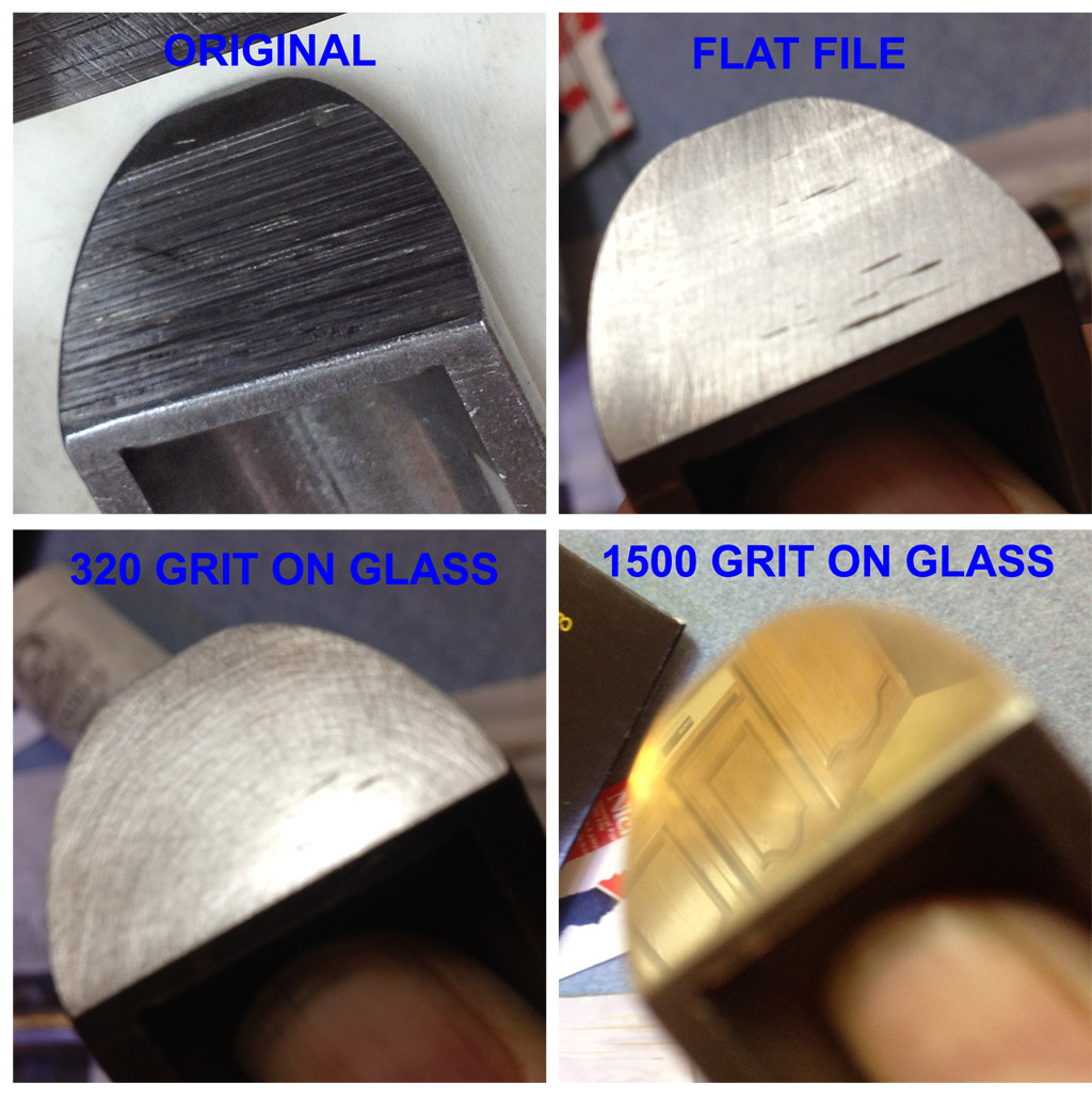
Here are the parts that rub on each other, compare them to the scored pictures above:
A couple days age, we got the Rack-And-Pinion housing back from plating.
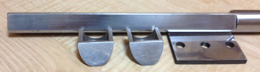
Here is a group shot of all the parts, ready to reassemble:
Passenger end parts:

Center parts:

Driver end parts, the rack, pinion and bearings. Ideally I would have replaced the bearings, but the needle bearing has an integrated seal and I did not feel like chasing that goose. There is some wear/pitting on the shaft, I think more likely from water/rust. What they got was a serious cleaning in solvent, and a good grease repack:

These are the parts that keep the rack forced into the pinion:

I wanted a "soft" stop on the end. There might have been a rubber stop in the original--if so it was badly decomposed. I cut a circle of rubber from the old boot, my reasoning being that that material should withstand the grease. The diameter of the circle is so it just fits snugly in the end of the tube and does not fall out. The thin material makes a nice positive "bump" stop, bit does not sound or feel like the slam of steel on steel. There is ~3 1/2 turns lock to lock with these stops in. I wonder what the original number of turns was?

On the passenger end, there is a solid steel plug/stop. It is held in place by a snap ring. Additionally, the mounting bolt goes through the bracket tube and plug:

I got the boot from Topline, and it appears to be good quality. I thought it was a little bit funny that the bag is marked "Germany" and the sticker is "Thailand":

Here is what the assembled unit looks like, from two angles:

I was not sure how to adjust things, but here is what I did:
1) move to the center of travel
2) tighten the screw until I could feel the gears bumping as I turned the pinion
3) backed off just to where the bumps cannot be felt
4) locked the adjusting screw
We will have to see how that adjustment works when the car is rolling.
Last edited by Baxsie on Fri Aug 08, 2014 12:27 pm; edited 1 time in total |
|
| Back to top |
|
|
Baxsie
Joined: 12 Apr 2012
Posts: 253
|
|
| Back to top |
|
|
ONEBADBUG
Joined: 25 Oct 2003
Posts: 440
Location: Spokane
|
| Posted: Mon Jan 21, 2013 8:26 am Post subject: |
|
|
| Super diff is always a good idea. I think you buy the extra spiders separately, I have always had used ones. Other than that, your original trans should be fine. |
|
| Back to top |
|
|
Baxsie
Joined: 12 Apr 2012
Posts: 253
|
| Posted: Tue Jan 22, 2013 10:18 am Post subject: |
|
|
We had a short time in the shop last evening.
Tried out the little super-cheap Harbor Freight detail HVLP gun. First time I've painted with a spray gun in 30 years. and that was only for a few minute with a primer gun. Well, for me, it seemed to work great. I am sure experts would disagree, but for my skill level it shot wonderfully. Use your 20% coupon
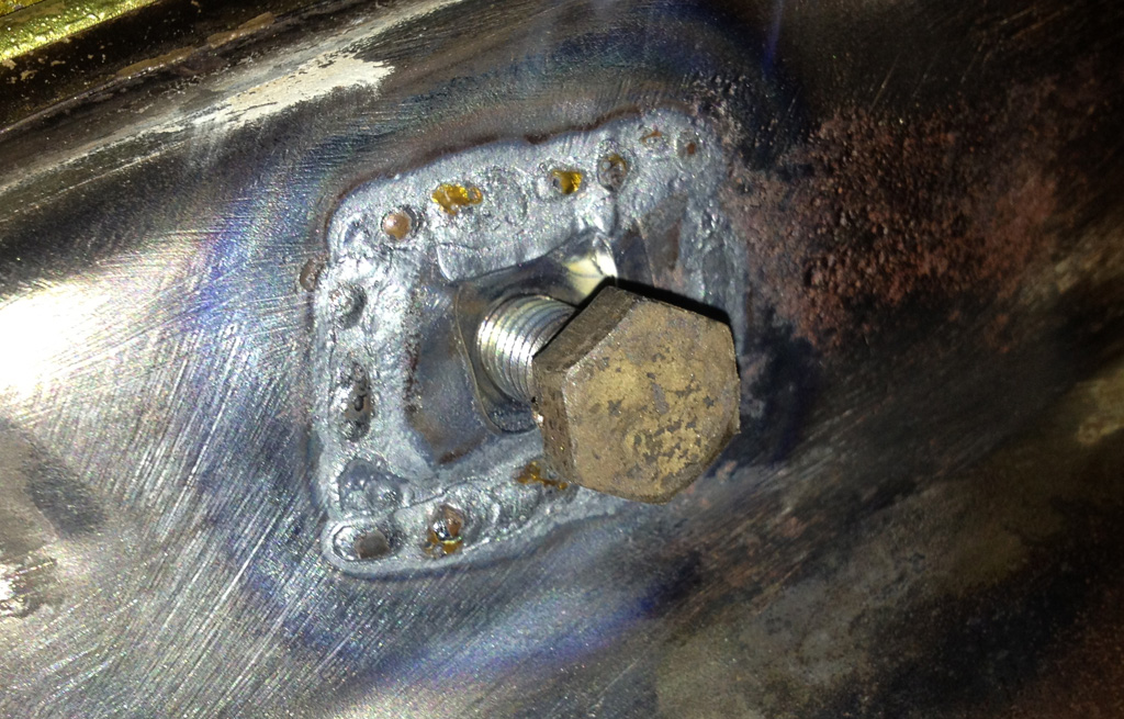
After cleaning up the gun, we decided to take on welding in some of the blown fender weld nuts.
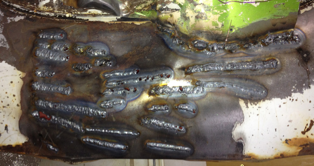
I have spent several hours trying to improve my MIG skills on thin metal welding. We got some of the super-fine 0.023 weld wire. I think I finally have a handle on adjusting the welder:
Here is the first nut. Eeek:
Before doing the second nut, we decided to grind the bumps off the back of the nut:
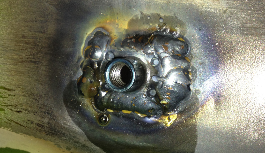
The second weld is not too embarrassing:

Same weld, brushed off:

Here is a shot from the back side. I think the penetration is good. These holes were so cracked and beat up, I think having a solid weld all the way around the fender nut will return a lot of the integrity to the metal in the fastener area:
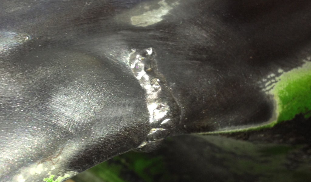
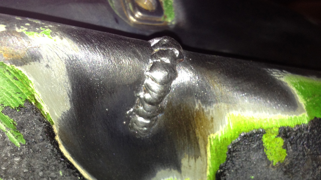
I was feeling so brave that I took on a crack. OK, it is under the fender so it was not so brave We will grind them down in any case.
Last edited by Baxsie on Fri Aug 08, 2014 12:28 pm; edited 1 time in total |
|
| Back to top |
|
|
|
|
You cannot post new topics in this forum
You cannot reply to topics in this forum
You cannot edit your posts in this forum
You cannot delete your posts in this forum
You cannot vote in polls in this forum
You cannot attach files in this forum
You can download files in this forum
|
|