| View previous topic :: View next topic |
| Author |
Message |
Baxsie
Joined: 12 Apr 2012
Posts: 253
|
 Posted: Tue Jul 02, 2013 10:40 am Post subject: Fabricating Front Bumper Shock Mounts Posted: Tue Jul 02, 2013 10:40 am Post subject: Fabricating Front Bumper Shock Mounts |
 |
|
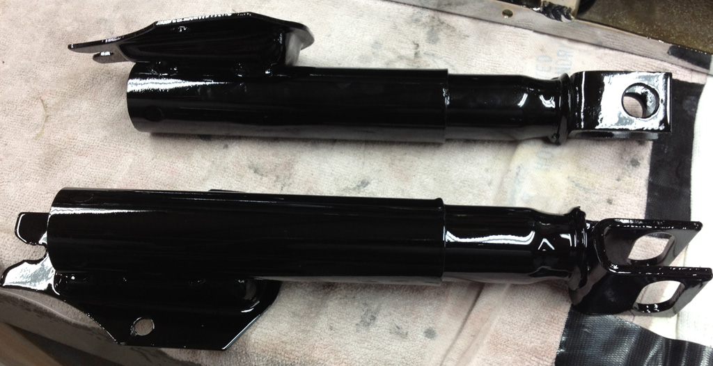
We used the "Grease Fitting" method of "fixing" the front bumper shocks. I would not say they are "fixed", but they are extended, and we have tested that they will compress, and actually rebound a small amount (video of a working VW super beetle bumper shock):
Adter the grease fitting, bead blasted, 2K primer and paint:
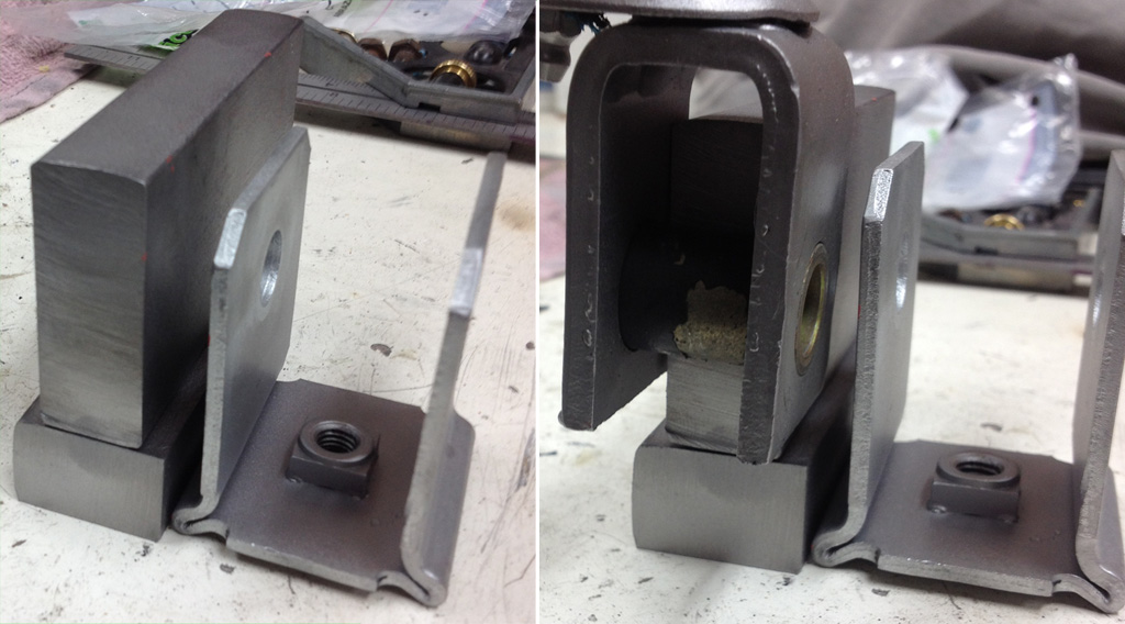
The original mounts interfere with the front bumper's daytime running light (DRL) mod, so we came up with an idea to make a mount that goes inside the shock's fork rather than outside it:
We used our cheapo HFT band saw to cut a chunk of the 2"x3/4" steel down to size:
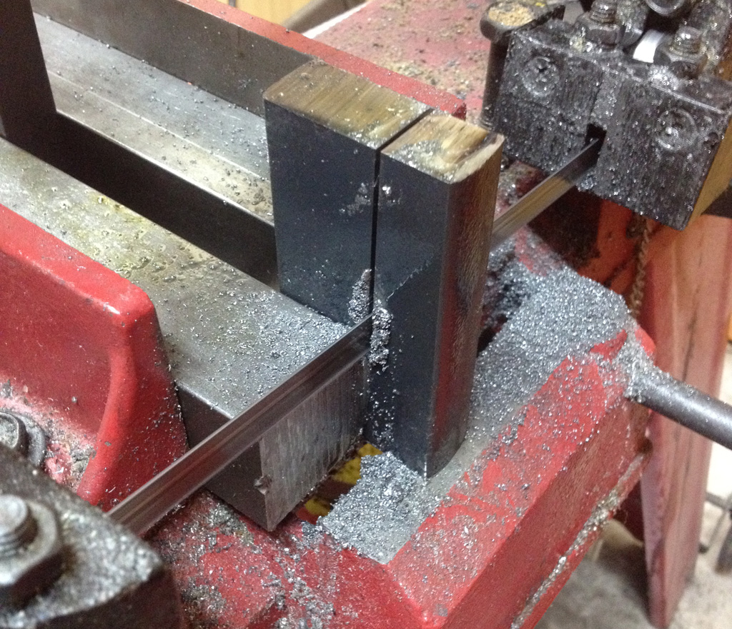
Used the stick welder to weld them, mainly so I could see if I still knew how to stick weld:

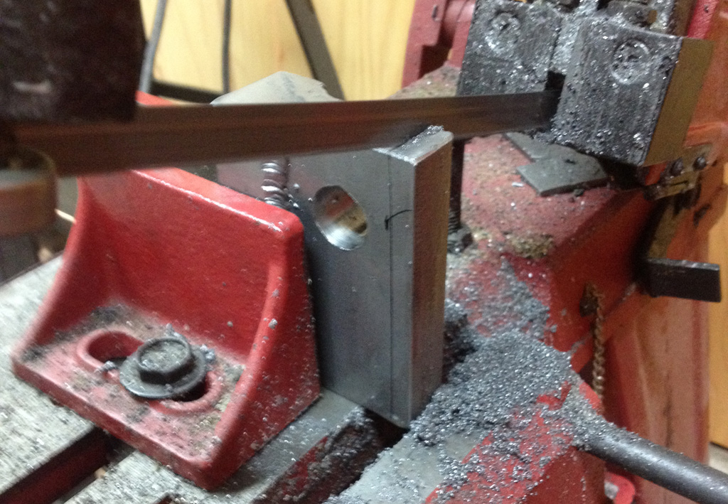
We then drilled a big hole for the bumper shock mount, and drilled and tapped two M8 holes for the bumper bolts. The mount was a little too high to rotate crrectly, so back to the band saw:
Then we decided it looked too chunky, and trimmed the corner off to make it look more sleek:

A test fit revealed interference on the weld bead, so we ground the bead down nice and smooth:
A coat of 2K primer, followed by black paint:

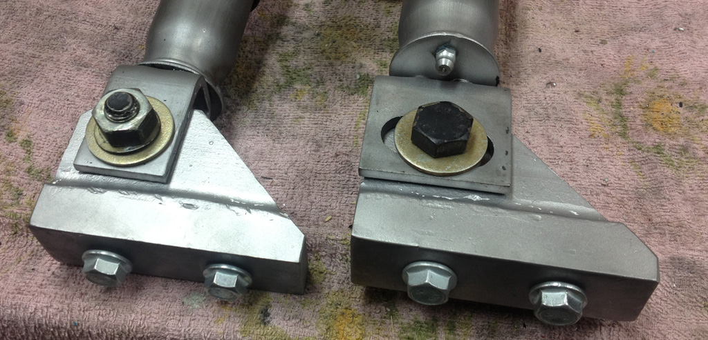
Here is how they look from behind. We did have to make the bolt head "D" shaped to clear the DRL bracket:
Larger view:
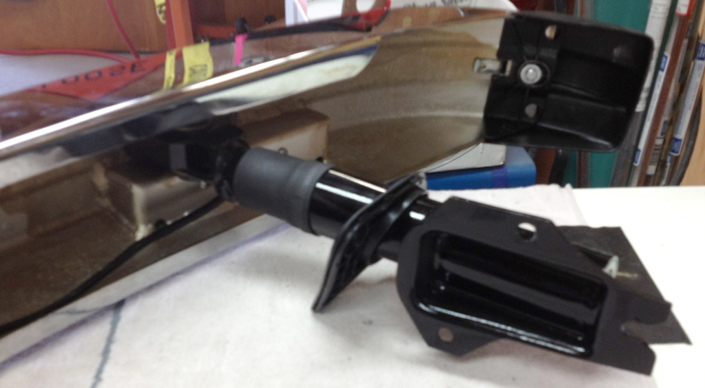
Here is the bumper in full trim, ready to mount to the car:

Last edited by Baxsie on Fri Aug 08, 2014 12:09 pm; edited 1 time in total |
|
| Back to top |
|
 |
Baxsie
Joined: 12 Apr 2012
Posts: 253
|
| Posted: Thu Jul 04, 2013 7:12 pm Post subject: Top Line Rear Disc Brake trial assembly |
|
|
We did a trial assembly of the Top Line Rear Disc Brake kit today. It went well 
Here is a picture of the passenger disc brakes side:

The driver side:
Close up of the caliper on the passenger side:
Close up of the caliper on the driver side:
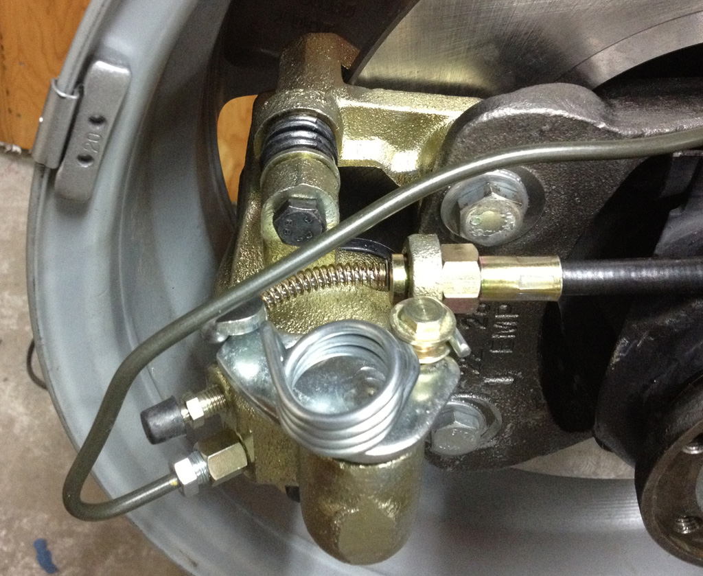
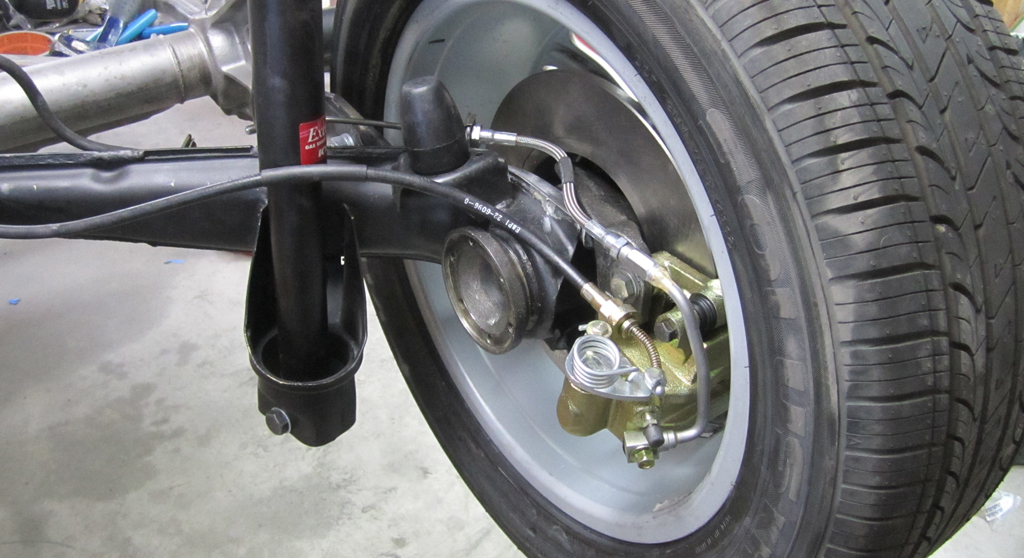
Here is how we routed the hard line. The line is quite a bit longer than stock, so we made a mount at the mid point:
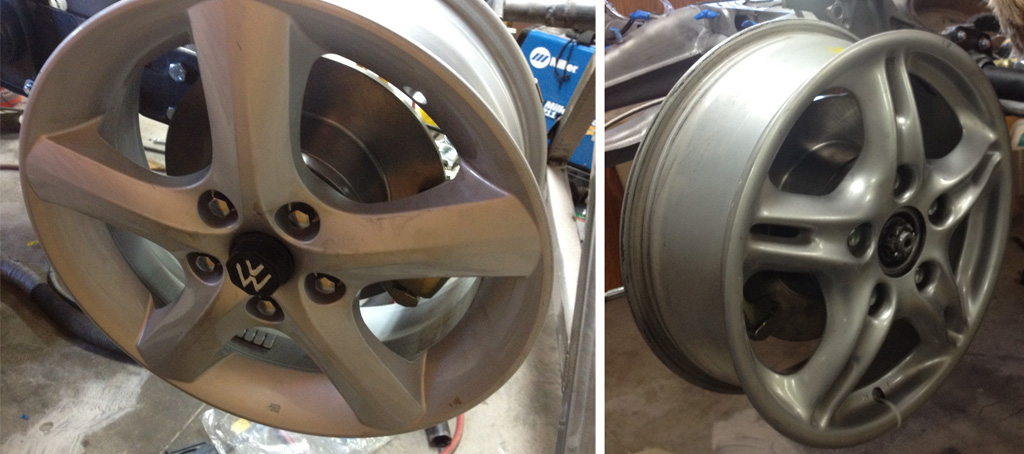
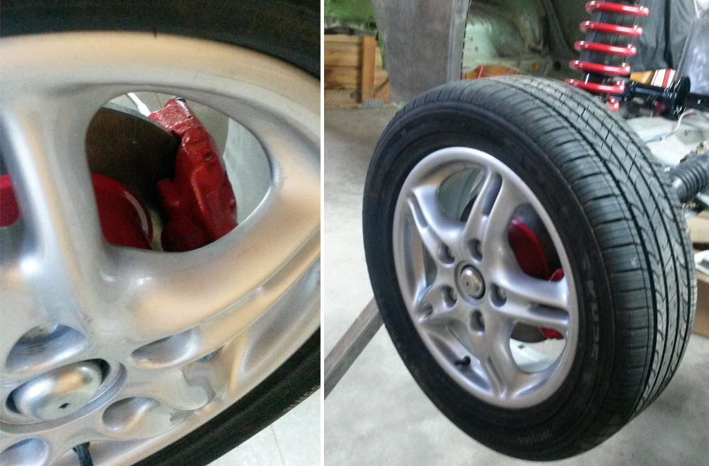
Here are the wheels we are using. The left image is one of the new Suzuki pull-offs, these will be for snow tires. The right is a front wheel from a Porsche Boxster. Both are 16x6, we plan to run 195/60 16 which should put us within 0.8% on the speedo reading.
Last edited by Baxsie on Fri Aug 08, 2014 12:09 pm; edited 1 time in total |
|
| Back to top |
|
|
Baxsie
Joined: 12 Apr 2012
Posts: 253
|
| Posted: Sat Jul 06, 2013 8:19 pm Post subject: Kumho Solus KH25 205/55R16 Tires |
|
|
Our plan was to use 195/60R16 tires, but that size is not very popular. After talking to our local Les Schwab tire place, we settled on some used (Dodge Dart new car take-offs) Kumho Solus KH25 205/55R16 Tires. Not exactly dream tires, but the price was good, and since they are used he agreed to take them back at no expense in case the size does not work out.
The tread is barely worn:

Here is a shot of the tires mounted on the chassis:

Last edited by Baxsie on Fri Aug 08, 2014 12:08 pm; edited 1 time in total |
|
| Back to top |
|
|
Baxsie
Joined: 12 Apr 2012
Posts: 253
|
| Posted: Sat Jul 06, 2013 8:43 pm Post subject: Rear Disc Brakes: Take two on the brake lines |
|
|
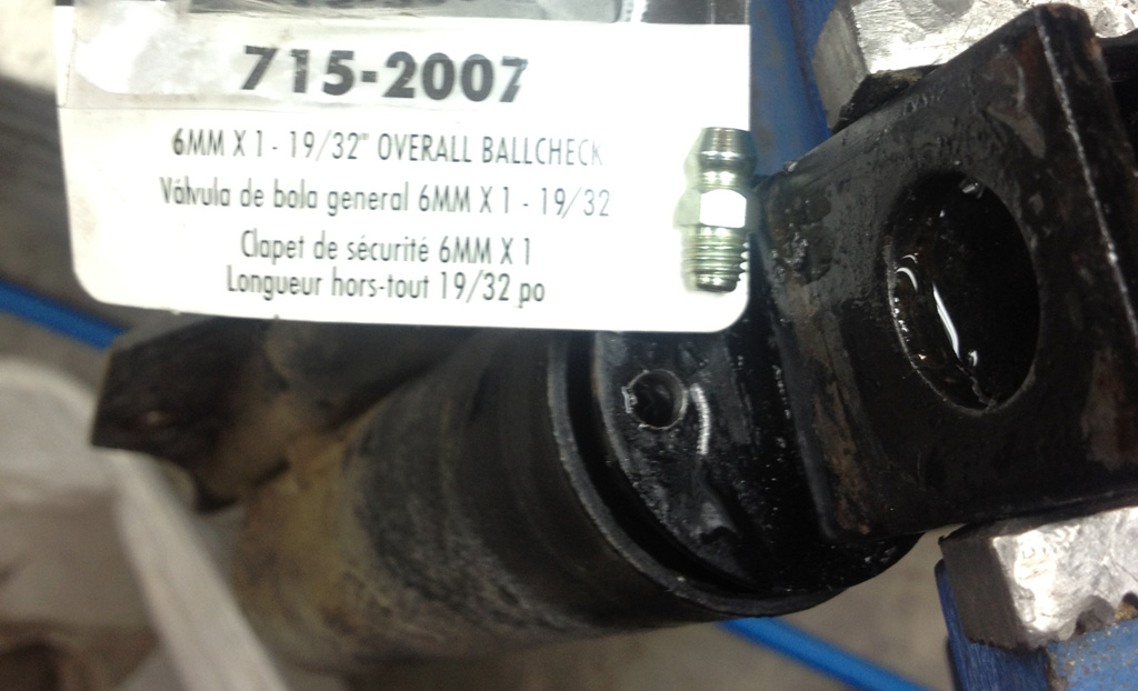
I was uncomfortable about two points of the rear disc brake line set up described two posts up. One was the way the small hard line jutted out of the back of the caliper. It just seemed fragile out there. The second item was that these calipers are floating, so they can move in relation to the axle mount. This only a small amount in normal operation, but if you had chatter or a warped rotor it might wiggle some. In any case, I did not like having hard line going from the floating caliper to the fixed axle housing.
We poked around at our local Auto Zone where the nice fellow let us paw through his brake line inventory. We found a line that had a banjo style fitting which is compatible with the caliper it along with several inches of very beefy brake line.
We bent that beefy brake line, and brazed a metric bubble coupler to the end. From there we used the short flex that Top Line supplied, running it to a new mounting tab (we will need to get two more of the short flex lines to go from the suspension arm to the body).
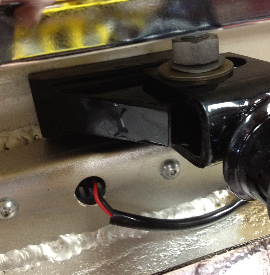
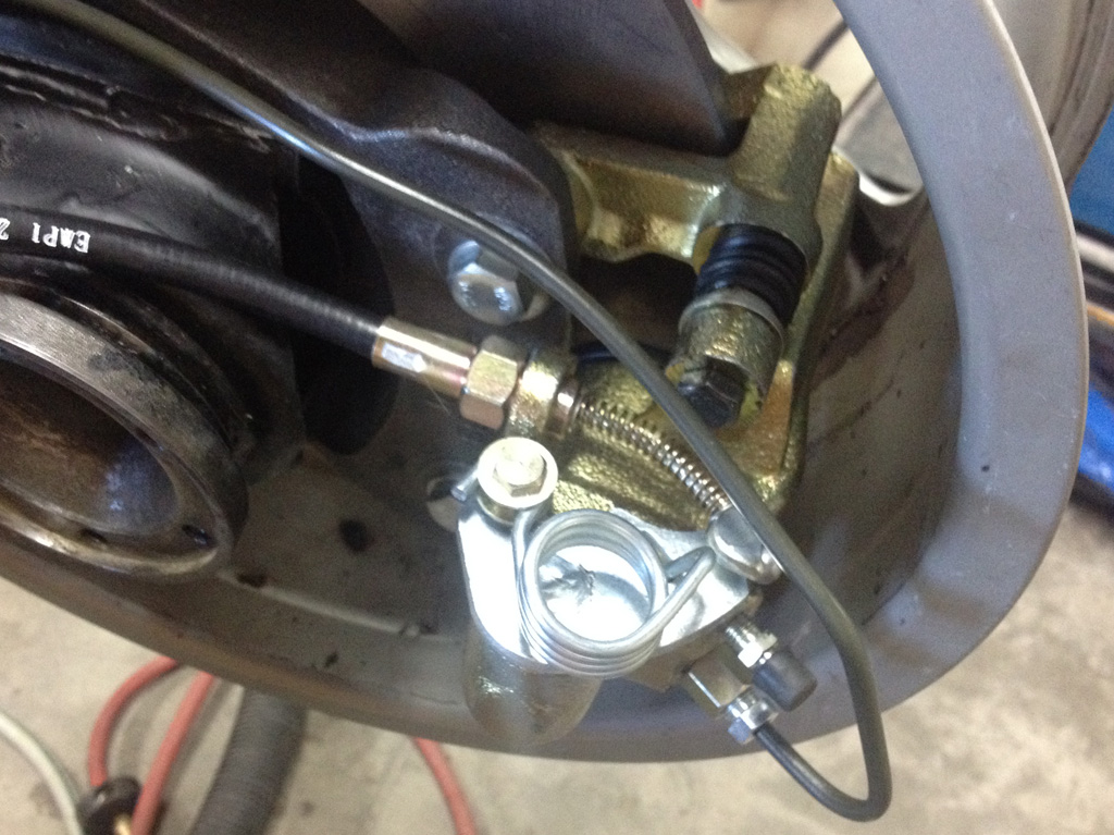
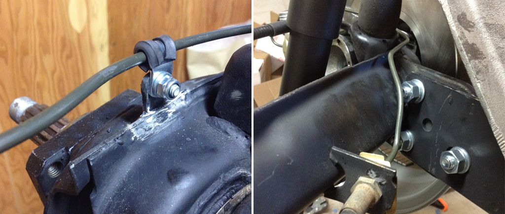
Here is the result:
Here is a close up of the heavy line / adapter we made:

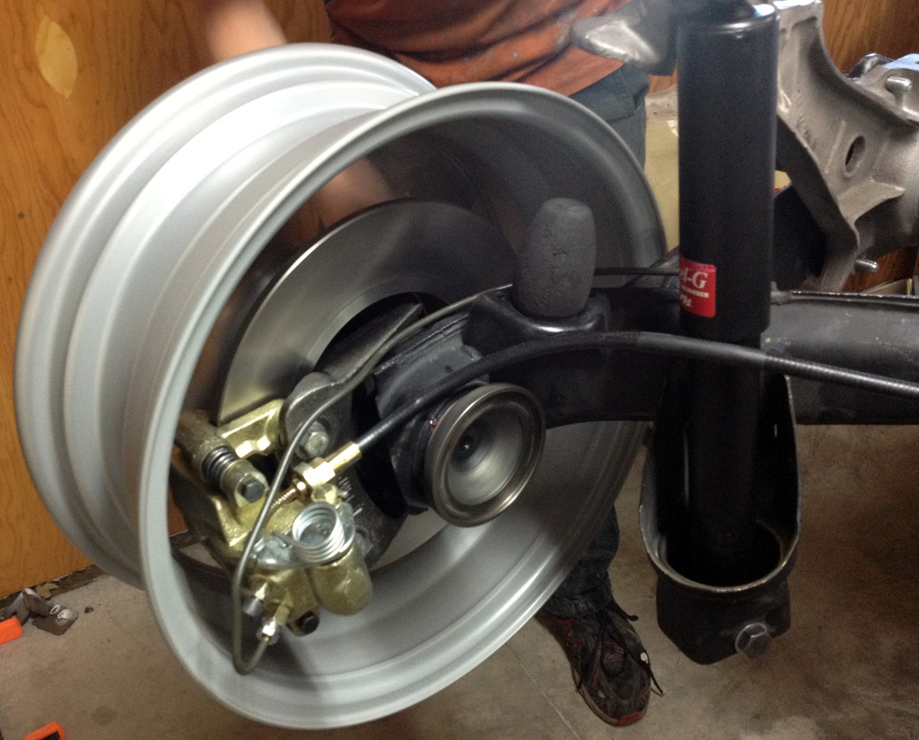
This image shows the short flex and the new mounting point:

Mirror image everything on the other side:

Last edited by Baxsie on Fri Aug 08, 2014 12:08 pm; edited 1 time in total |
|
| Back to top |
|
|
Baxsie
Joined: 12 Apr 2012
Posts: 253
|
| Posted: Sat Jul 13, 2013 9:26 pm Post subject: Bow-Wow Auto Parts Inc. in Boise, ID |
|
|
Visited Bow Wow in Boise. This shop built my 1835 ~32 years ago. Still in business, still full of VW parts
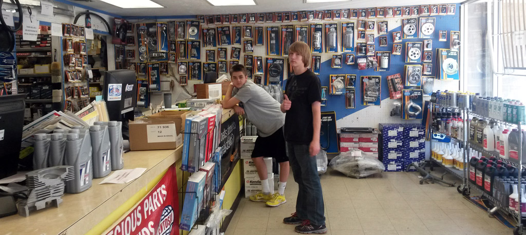
http://www.bowwowautoparts.net/
Last edited by Baxsie on Fri Aug 08, 2014 12:07 pm; edited 1 time in total |
|
| Back to top |
|
|
Baxsie
Joined: 12 Apr 2012
Posts: 253
|
| Posted: Sun Jul 21, 2013 10:18 am Post subject: Painting CB Performance 1702d C-Channel Valve Covers |
|
|
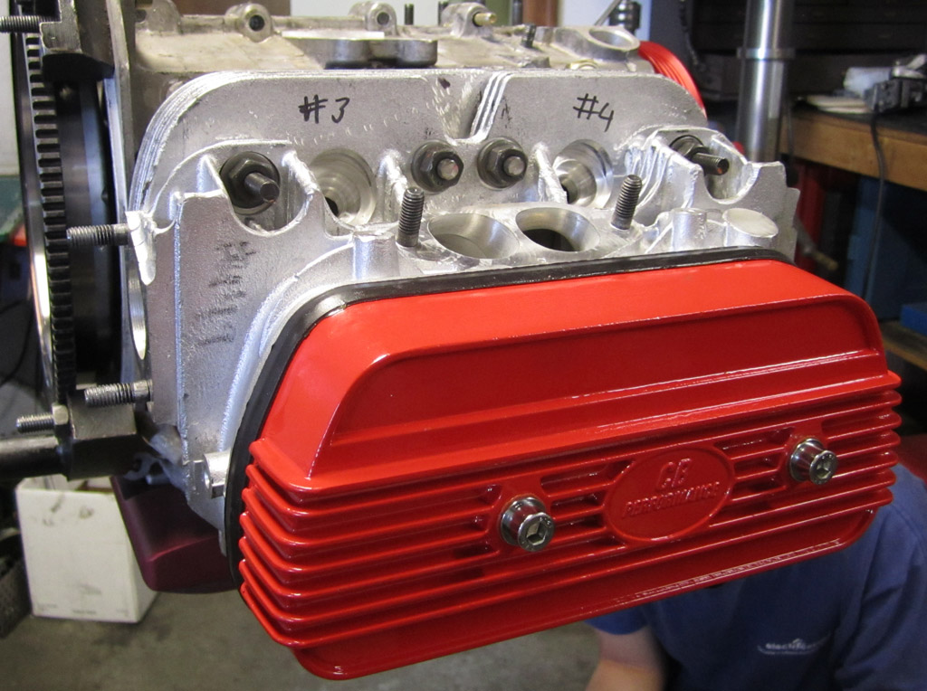
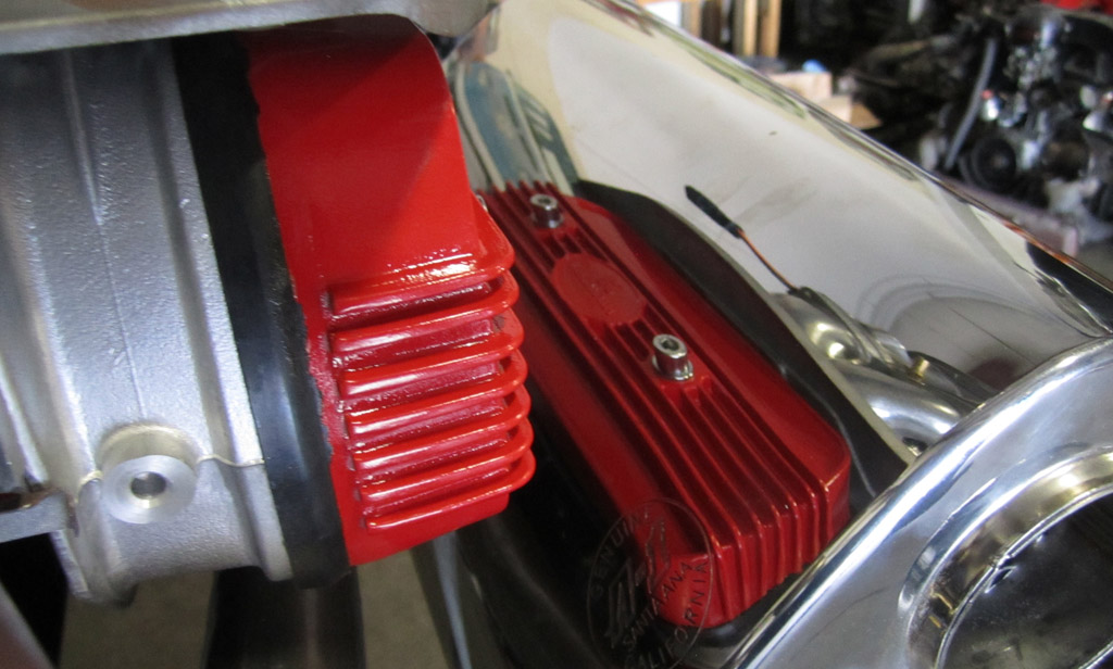
We have the CB Performance 1702d C-Channel Valve Covers:
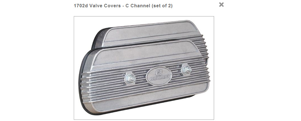
I kind of thought they would be clear anodized (not that the descrition promises it), but they are coated with a clear of some kind. In hopes of getting them bright red anodized, we used paint stripper to remove the clear and then cleaned them. The metal was very dark and blotchy:

The folks at the anodizing shop said they could try, but the best case would be that the the anodizing would be very dark, worst case it would contaminate their process. There is some additive to the aluminum to make it flow well into the molds, that comes out when anodizing is attempted.
So we decided to go with with "Fire Red" RustSeal MotorCoater that we had on hand for the disc brake calipers. The MotorCoater is supposed to be good for high temps. In any case it looks nice:

The stock CB setup for hold down is a stud through the valve cover, with a red sealing ring, washer and locknut (on left). It seems to me that the oil could seep through the threads. We are going to try a socket head that has a smooth section just below the head (on right). This should give the seal a smooth shaft to seal against. I think we will have to shorten the bold though.
Things to watch our for:
1) there are some mold marks on the sealing lip of the valve covers. We used a large flat belt sander to "plane" the bottom edge of the valve covers perfectly flat.
2) the MotorCoater application MUST be preceded by the AquaClean and RustBlast, and takes a LONG time to cure. 4 days or more, even in this hot weather. You can touch it and it seems dry, but press on it hold, and it will leave a mark 
Last edited by Baxsie on Fri Aug 08, 2014 12:07 pm; edited 1 time in total |
|
| Back to top |
|
|
Baxsie
Joined: 12 Apr 2012
Posts: 253
|
| Posted: Mon Jul 22, 2013 3:45 pm Post subject: Replacement Super Beetle Spring Pad |
|
|
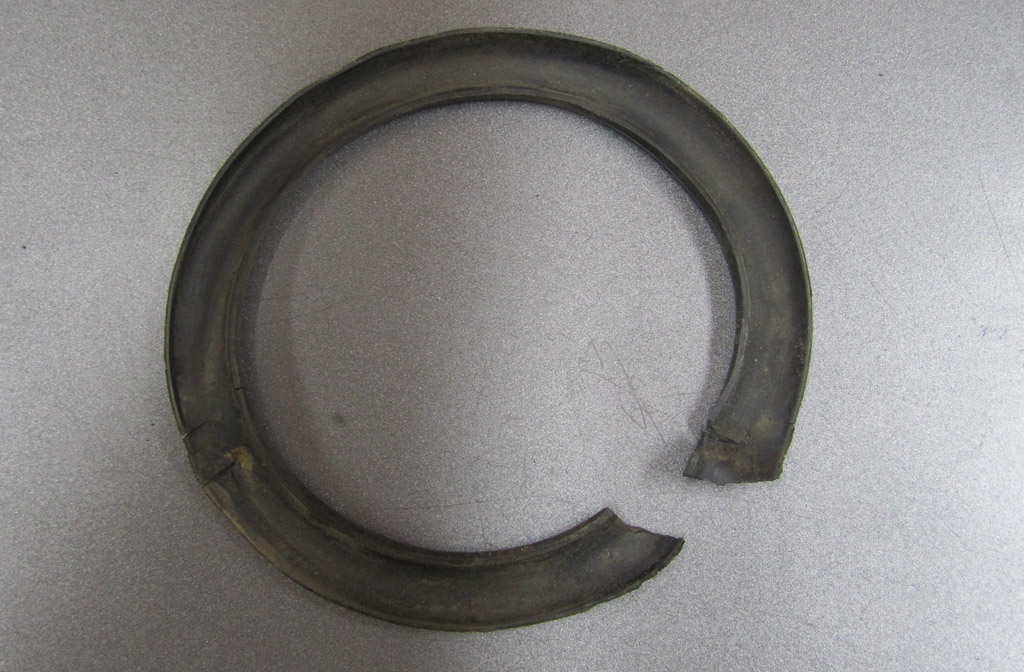
The springs around the super beetle front struts originally have a rubber pad to cushion between the spring and the pieces that cradle the springs ends. Most were missing, but I did have one that kind of survived:
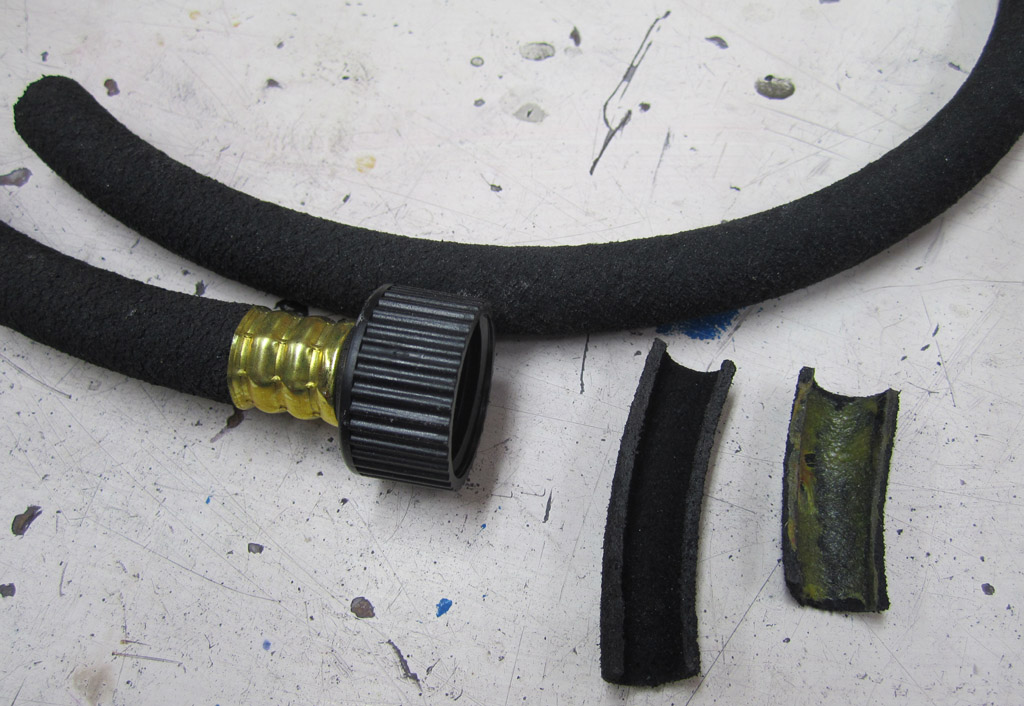
It looked like some of that black rubber (made from recycled tires) soaker hose might work. It is not real strong, but I think the compressive strength will be OK. We split a section long enough to go around the TopLine Sport+ Spring. Here are some scraps showing what it looks like, native, split and prepped with weatherstrip adhesive:
The weatherstrip adhesive holds the split soaker hose on well:
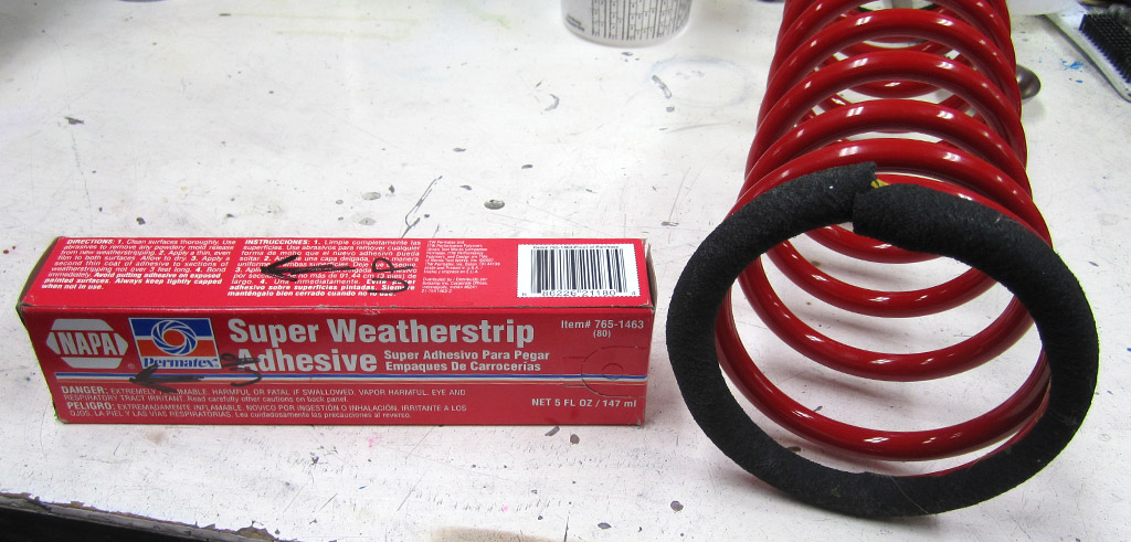
There were marks from the sharp end of the OEM spring digging into the metal of the cradle. It almost looked like it ratcheted around. We radiused the end of new spring a bit in an effort to protect the pad:

Last edited by Baxsie on Fri Aug 08, 2014 12:06 pm; edited 1 time in total |
|
| Back to top |
|
|
Baxsie
Joined: 12 Apr 2012
Posts: 253
|
|
| Back to top |
|
|
Baxsie
Joined: 12 Apr 2012
Posts: 253
|
| Posted: Mon Jul 22, 2013 10:19 pm Post subject: 2085 Engine Mock Up, Tin questions |
|
|
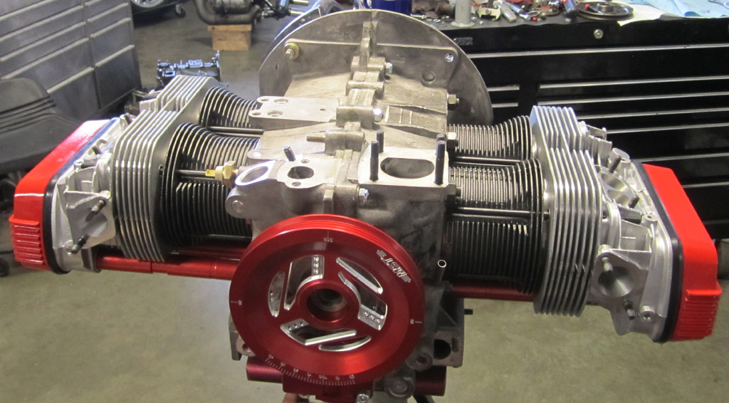
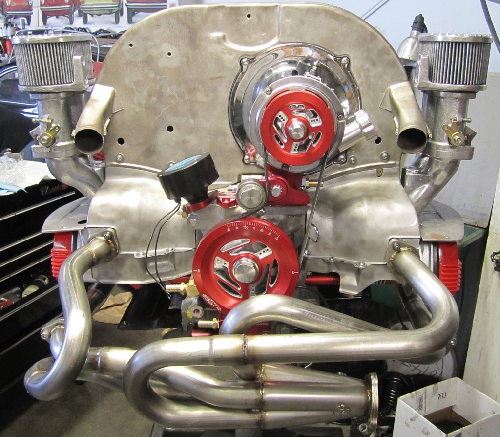
Tonight we mocked up or test-assembled the engine. We wanted to make sure all the tin fit, and needed to sort out the heat exchanger situation so we could run the car at the "real" build at ProVolks next week.
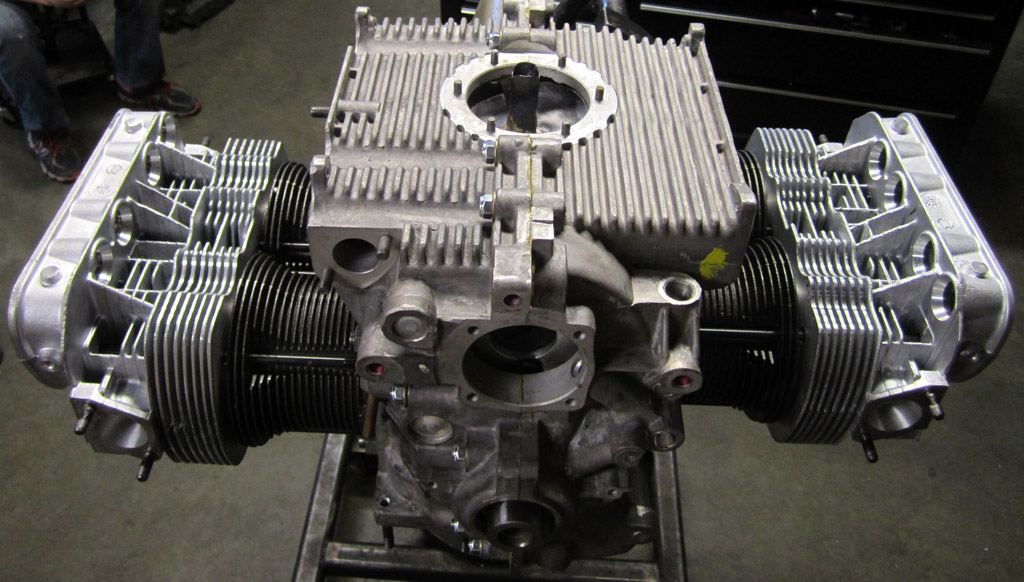
You gotta start somewhere:
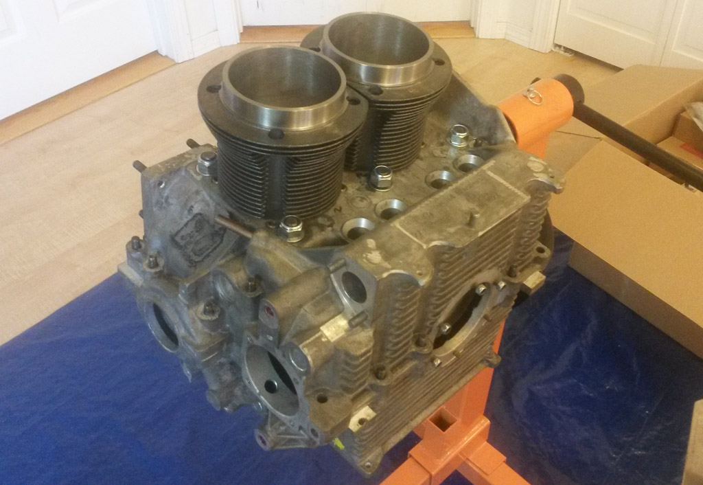
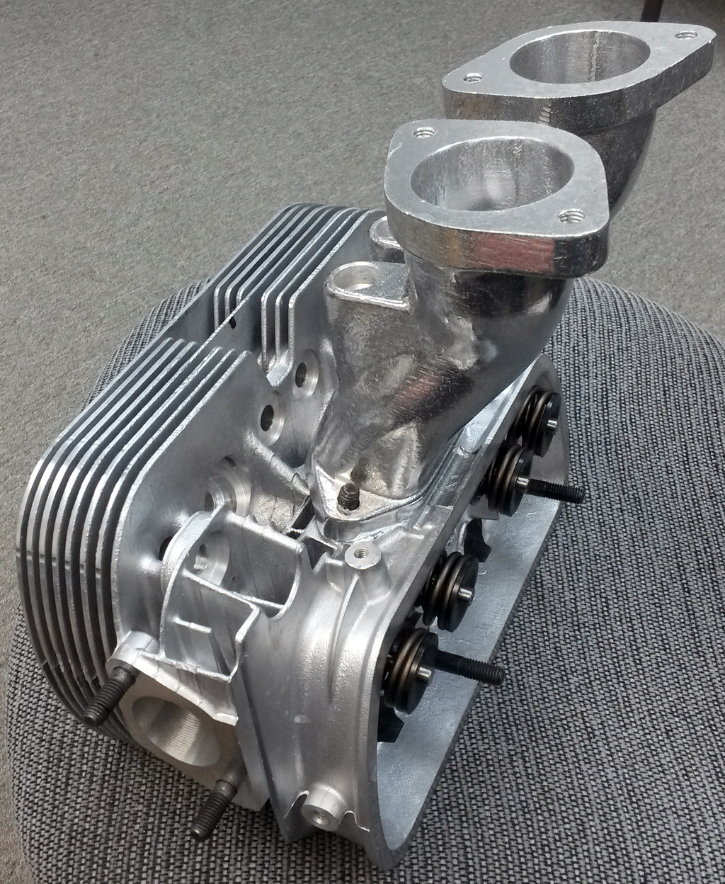
This is the rare VW air-cooled inline-two cylinder prototype that the eventually became the rabbit engine:

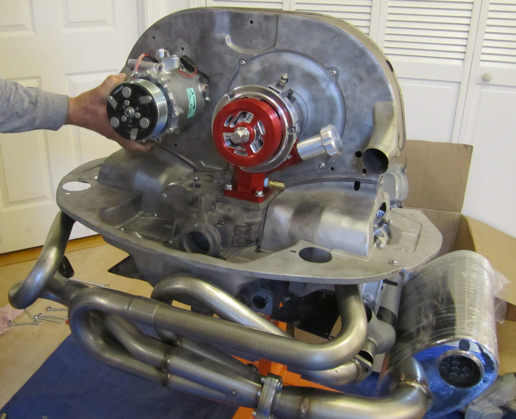
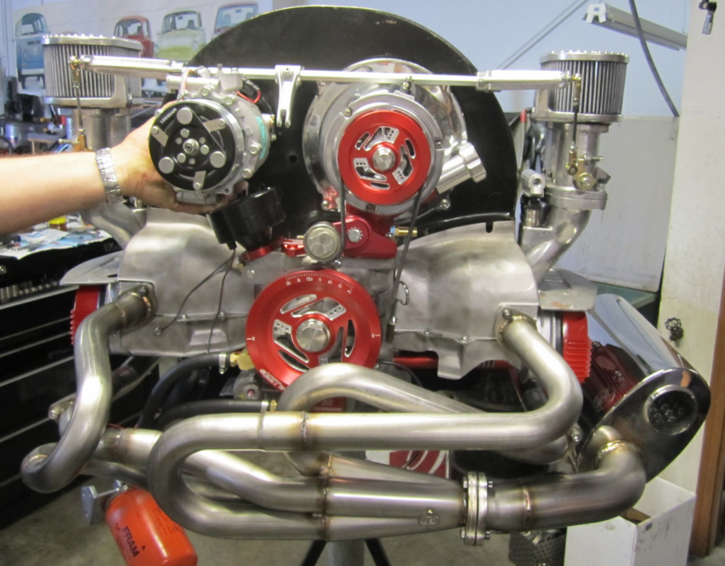
Once the tin was installed, and the dress-up alternator and stand was on, we checked to see if the idea of putting the air conditioning compressor at the same height as the alternator would work. Does not look easy, but does look possible:
NOW FOR THE QUESTIONS
Question #1: The head studs seem to be uniformly too long. I read somewhere to only hand tighten them into the case savers, which I did. But the studs seem to interfere with the sheet metal in several places. I am pretty sure I have the long, short and mediums in the right places. That is pretty obvious once you see the different levels on the head.
These are the CB CroMoly stud kit. Maybe they are extra long for stroked engines? Is there a "standard" stock length that I could check these against?
Question #2: The fan rubs against the alternator backer plate. Is that clearance super tight? There were three shims in the fan hub mount kit, but even with those installed the fan still rubs.
Since the fan, alternator and fan hub are all new, I am not sure what to suspect first.
Question #3: I think all the tin is on, but the rear of the engine seems very open . . . like it may be missing something. Can you look at these pics and let me know if all the tin that is supposed to be there is there?

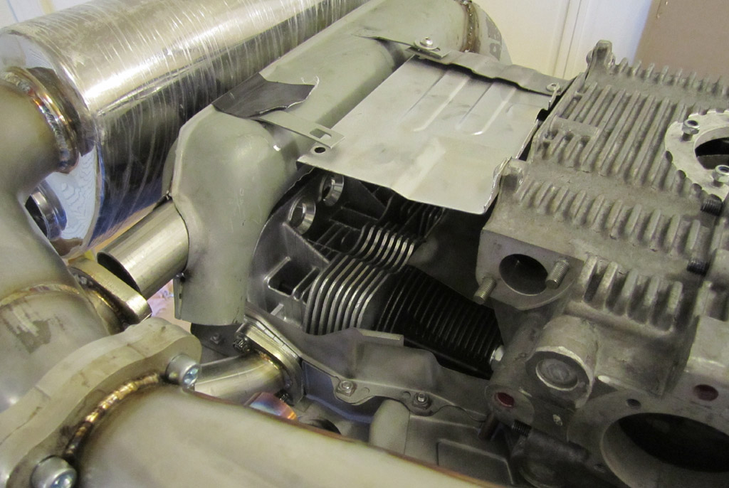
Thanks in advance for any help you can offer.
Last edited by Baxsie on Fri Aug 08, 2014 12:06 pm; edited 1 time in total |
|
| Back to top |
|
|
Baxsie
Joined: 12 Apr 2012
Posts: 253
|
| Posted: Tue Jul 23, 2013 6:20 pm Post subject: |
|
|
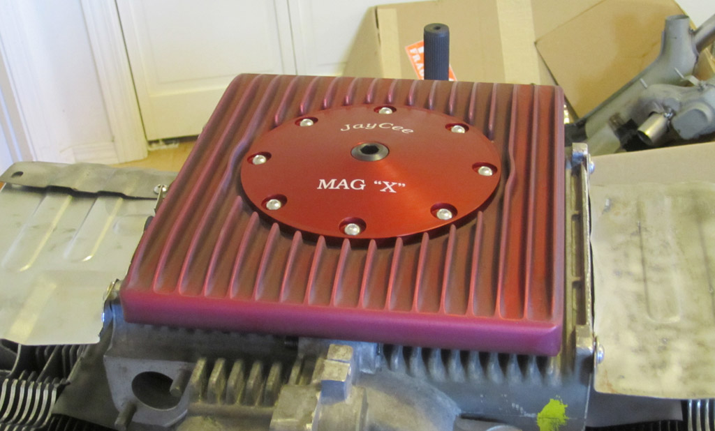
Got the parts back from the anodizing. The sump is rather purple because additives to the aluminium to make it better for injection molding make it a not as good candidate for dying, however it's still looks decent, and should provide a nice bit of protection and color. Instead of using the stud/socket caps sent with the sump, we decided to use some left over stainless steel screws from the engine tin.
Last edited by Baxsie on Fri Aug 08, 2014 12:05 pm; edited 1 time in total |
|
| Back to top |
|
|
Baxsie
Joined: 12 Apr 2012
Posts: 253
|
| Posted: Wed Jul 24, 2013 8:53 pm Post subject: |
|
|
| cortexgunner92 wrote: | Hey all, first post in this thread actually, I've been stalking for awhile but now I decided to come from the shadows. Anyway, baxie's son here. So..yeah..
Earlier in the year we got some switches from a junked Passat, they don't look too modern and out of place and they are from a former VDub so I thought they'd be a good match(plus there was a full set!).
Space will be limited on the dash...I purchased a stereo+two seven band equalizers today, the total size of all these will be = to a double DIN. One EQ will control the front two speakers, and tweeters, and the other one will control the rear 6x9s and the sub. Being the audiophile I am I like to have complete control over many frequencies, plus I listen to music on very different ends of the spectrum(primarily classic rock and house). More on the audio setup I am planning once I acquire the rest of it 
Anyway, to free-up some much needed dash space for other controls, I wanted to integrate the window controls into the armrest, as many modern cars have. I wasn't very careful this first time, so the result isn't very pretty, but I have new armrests and I'll get some practice in on the 50 old and cracked ones lying around before I touch those...
Apologies for the photo quality...my phone's getting old...
-NOT PICTURED-
Before I dremeled, I traced the switch, and scored the area with a box knife. It made a checkerboard pattern, this made removing the first layer of material very easy and controllable...it only went downhill from there though...
I used a dremel to cut out most of the foam, and the ridges on the collet ended up eating it away where it touched for too long, that's why it doesn't meet perfectly at the edges, I'll look for a collet without ridges or sand these ones off to try again...

The bottom, made clearance for the wires to tuck

The hole is a lot more rough than I would like, I was having a hard time keeping the dremel from catching and getting stuck, digging very deep in a certain direction. I think to do this for real I'll dremel most then burn the foam out around the critical edges

Here it is on the door! Doesn't look too bad from a distance

The wires tuck under nicely, wrapping some black tape around them will help them blend in as well I think
 |
|
|
| Back to top |
|
|
Baxsie
Joined: 12 Apr 2012
Posts: 253
|
| Posted: Wed Jul 24, 2013 8:54 pm Post subject: Mockup of Front Suspension and Disc Brakes |
|
|
While cortexgunner was working on the window switch (nice job, BTW) I assembled the front suspension yet again. It all went together right this time
He painted the calipers (very carefully, with a brush) and I sprayed the hub of the rotor. We used RustSeal Motor Coater which is supposed to be good for high temps. This red combined with Topline's bright red Sport + springs makes it look pretty fun:
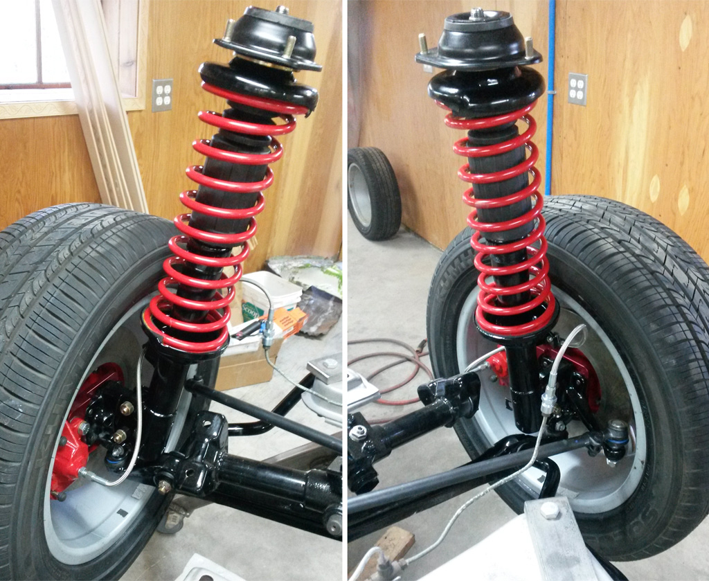
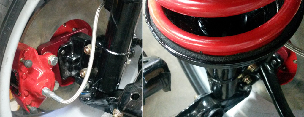
We used the Topline front disc kit, but substituted AC Industries blank rotors. They almost work together. We had a brake shop turn a bit off the AC rotor, and ended up adding two thin shims under the inboard bearing's outer race. It is bang on now. The topline caliper brackets are clear anodized, we got them red anodized for protection and color. We added a bracket welded to the strut tube to hold Topline's brake clamp.
The right shot shows how the soaker hose rubber pad looks. It tucks in perfectly between the sping and the spring plate:
Here is how it will look from the curb. I love the semi-hidden red accents. Still need to come up with some kind of a finish hub cap:
Last edited by Baxsie on Fri Aug 08, 2014 12:05 pm; edited 1 time in total |
|
| Back to top |
|
|
Baxsie
Joined: 12 Apr 2012
Posts: 253
|
| Posted: Wed Jul 31, 2013 1:44 pm Post subject: Father / Son Engine Build at Provolks: Day 1 |
|
|
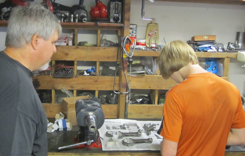
Well, we made it to Anacortes, WA to meet with Nate (aka AirCooledTechGuy) at ProVolks for the engine build. Nate is a natural teacher and my son is soaking it up like a sponge. I'm left to clean the occasional part, and now that I have some internet access I can post some pictures.
Photostorm approaching !
Placing the rod bearings in the rods:
Torquing the rods:
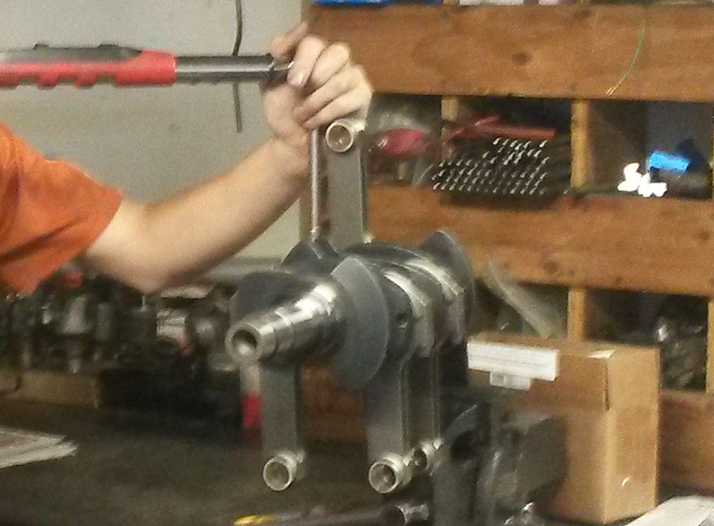
Video of checking the friction of the rod bearings . . . fun:
http://www.youtube.com/watch?v=pb6Eybewryc
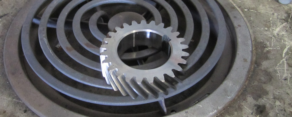
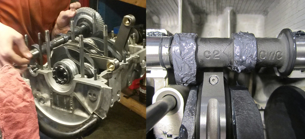
Pre-hearing the cam gear so it will slip on the crank:
The cam gear maby not look hot, but the IR image shows it is nice and toasty:
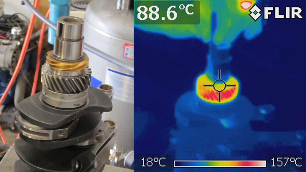
Laying the crank into the case:
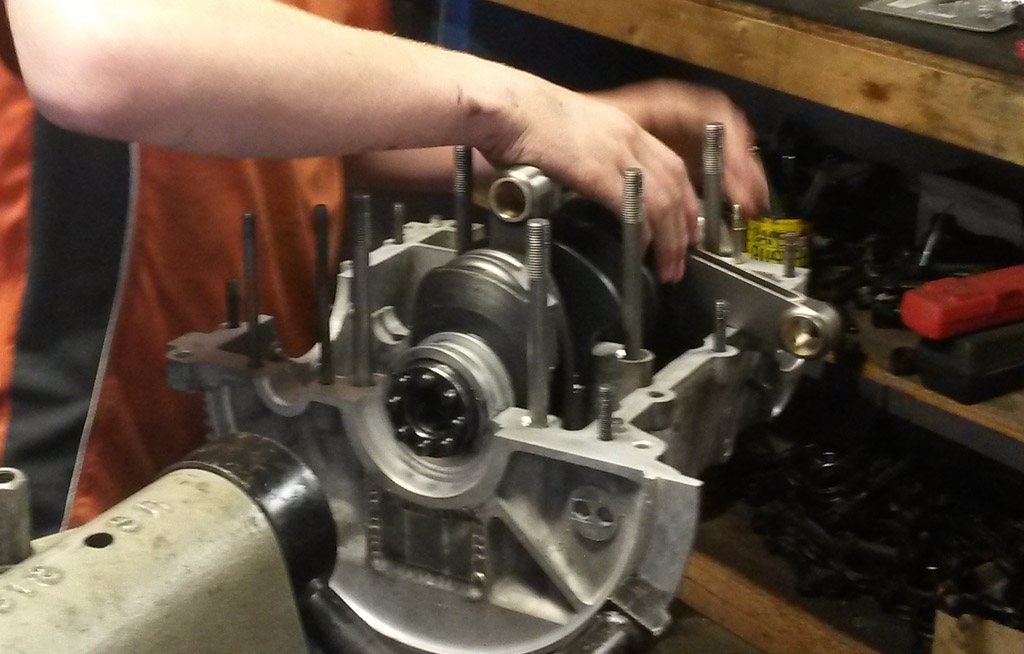
Putting the cam into the case. Lots of cam lube;
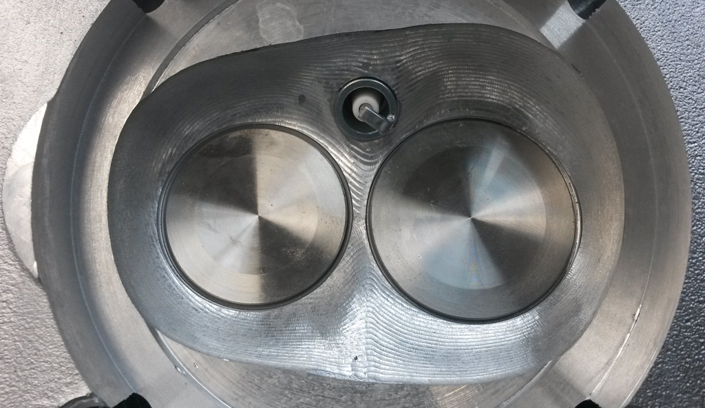
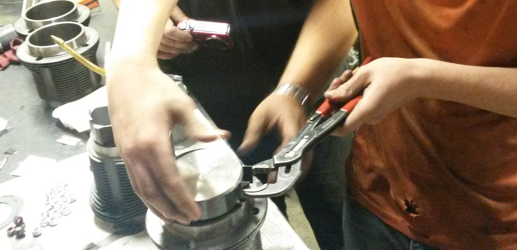
Compressing the rings:
Torquing the heads:
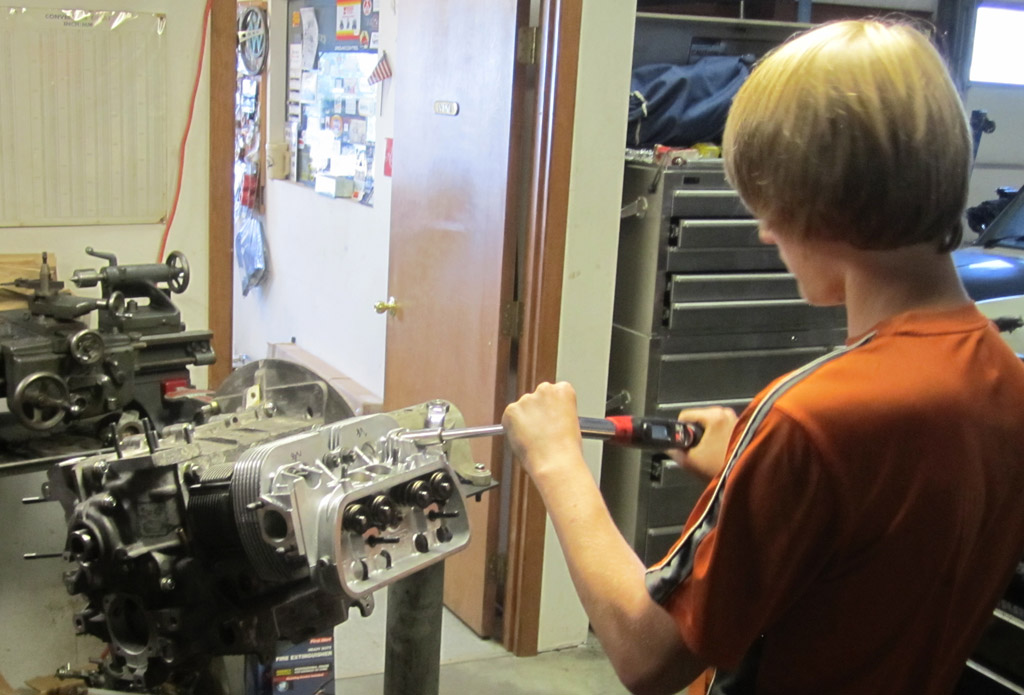
Starting to look like an engine:
Last edited by Baxsie on Fri Aug 08, 2014 12:04 pm; edited 1 time in total |
|
| Back to top |
|
|
Baxsie
Joined: 12 Apr 2012
Posts: 253
|
| Posted: Wed Jul 31, 2013 2:43 pm Post subject: Father / Son Engine Build at Provolks: Day 2 |
|
|
More engine build photostorm!
Dress-up MST Pushrod Tubes installed:
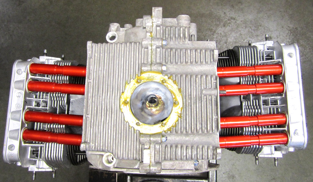
This is the CB thin-line sump, except we did some smoothing on it and had it anodized:
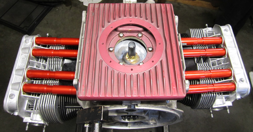
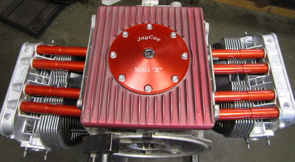
The trick Jay-Cee Mag-X sump plate:
CB oil pump with dress-up cover:
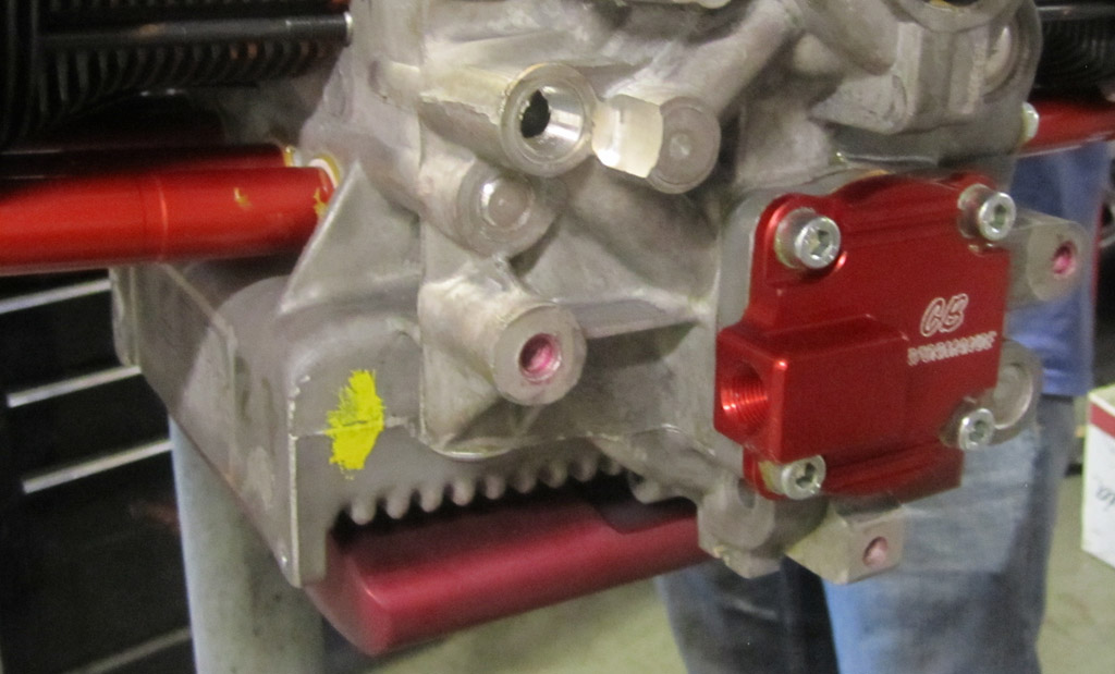
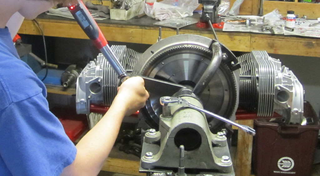
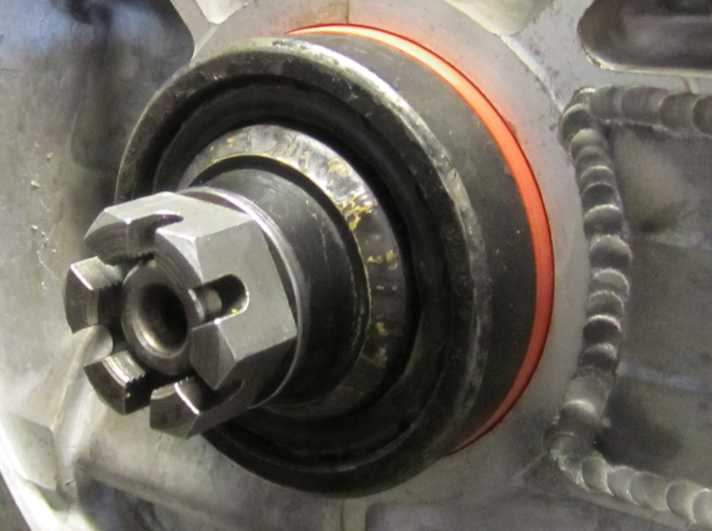
Enough fluff, back to the serious stuff. Setting up the end play with the shims:
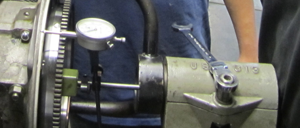
Torquing the gland nut, using a torque multiplier. The final install used a conventional torque wrench with the 38mm socket for the monster CB gland nut:
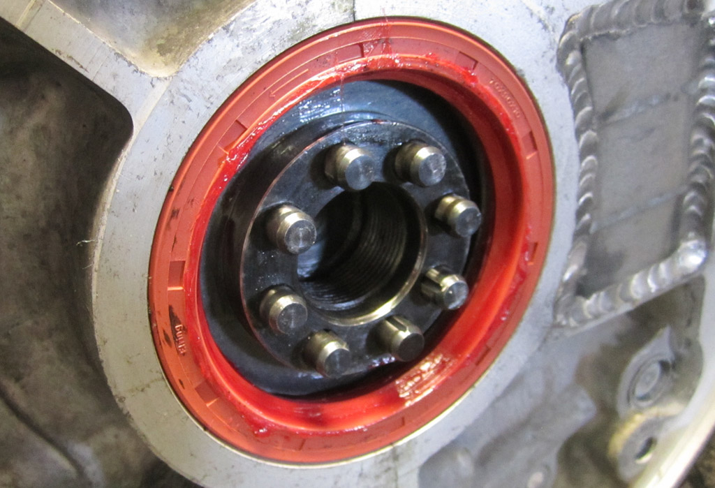
Nate has been doing this a long time, so he had his own home-made seal installed made from a gland nut, the end of an axel and an old bearing. Very clever
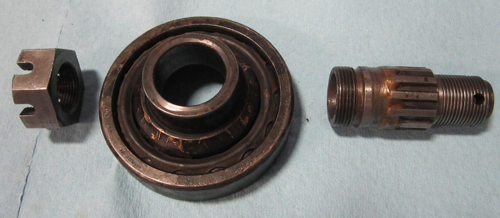
Seal tool in use:
Main seal installed:
Setting up the side-to-side positioning of the rocker arms:
The shim stack under the rocker arms after setting the valve geometry:
Last edited by Baxsie on Fri Aug 08, 2014 12:04 pm; edited 1 time in total |
|
| Back to top |
|
|
Baxsie
Joined: 12 Apr 2012
Posts: 253
|
| Posted: Thu Aug 01, 2013 9:35 pm Post subject: Father / Son Engine Build at Provolks: Day 3 |
|
|
Welcome to day 3 of the Father-Son engine build at ProVolks.
We rough cut the pushrods with a tubing cutter (tubing cutters can go through CroMoly?) and then squared them up on the sander:
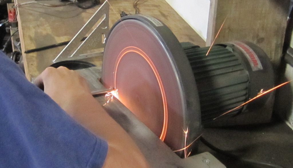
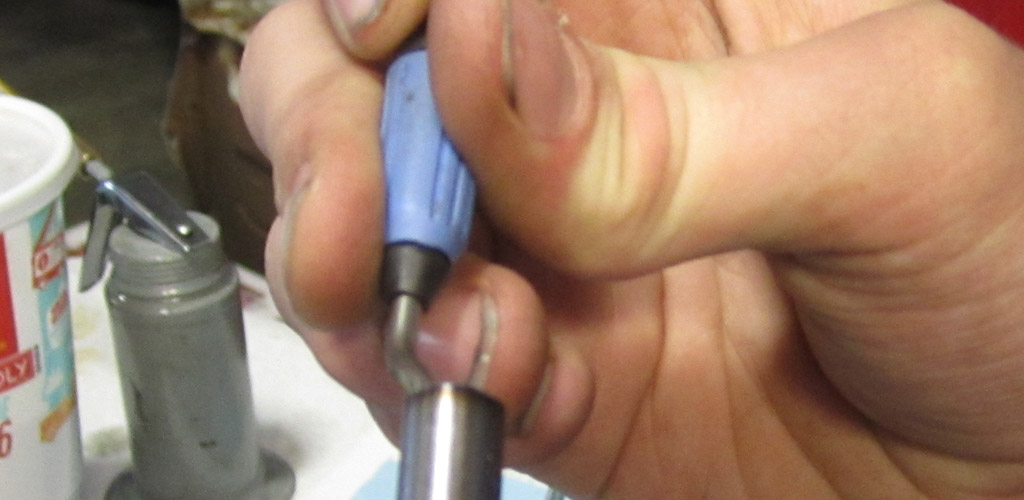
A quick pass on the wire wheel to de-burr the outside, then a final de-burr of the end of the tube:
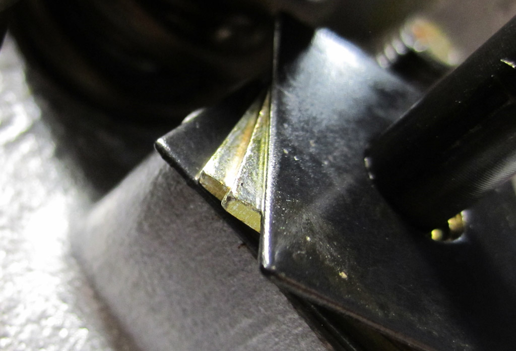
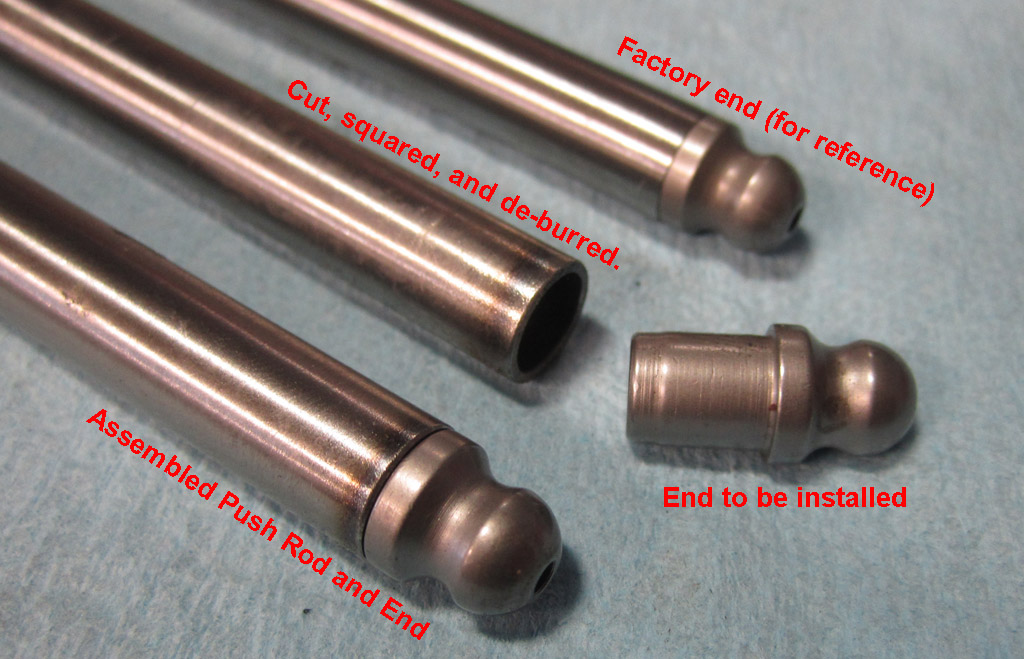
The top image is the "factory end" the bottom image is our "custom end":
Pushrods are installed and lifters adjusted in this shot:
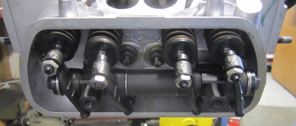
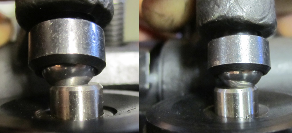
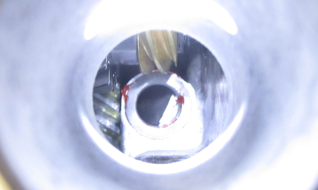
We found some trick chrome plated socket head bolts and washers. These still have an unthreaded section just below the head that we think will seal splendidly with the seal in the valve cover:
Overall progress shot:
Did you know that there are washers under the distributor drive gear? I do now:
The distributor drive gear turns the Cam Sync, which the MS3Pro (MegaSquirt) will use to sequence the spark and injection on a per-cylinder basis:
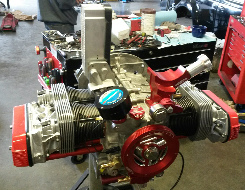
This is the last photo with the "modern" tin installed. The Fuel rails intersect with the tin, so we will have to modify that a bit to clear the rails:
Luckily, Nate had a "workable" "36 horse" doghouse tin. It will keep it cool through break-in:
Here is a mock-up of where we think the A/C compressor can mount:
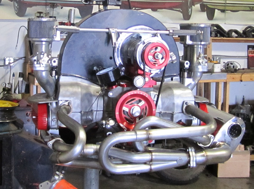
The stainess steel muffler from A1 is teh shiny:
We put it to bed on the test stand. Ready for some MegaSquirt magic in the morning:
Last edited by Baxsie on Fri Aug 08, 2014 12:03 pm; edited 3 times in total |
|
| Back to top |
|
|
|
|
You cannot post new topics in this forum
You cannot reply to topics in this forum
You cannot edit your posts in this forum
You cannot delete your posts in this forum
You cannot vote in polls in this forum
You cannot attach files in this forum
You can download files in this forum
|
|