| View previous topic :: View next topic |
| Author |
Message |
Baxsie
Joined: 12 Apr 2012
Posts: 253
|
|
| Back to top |
|
 |
ONEBADBUG

Joined: 25 Oct 2003
Posts: 440
Location: Spokane
|
 Posted: Tue Jan 22, 2013 7:09 pm Post subject: Posted: Tue Jan 22, 2013 7:09 pm Post subject: |
 |
|
| It's pretty straight forward. Yes to new seals, you can buy a whole kit, but output flange seals are separate I think. Limited slip diff is not needed because a bug has so much weight on the rears. Autocross is the only place you would notice it. |
|
| Back to top |
|
|
Baxsie
Joined: 12 Apr 2012
Posts: 253
|
| Posted: Wed Jan 23, 2013 10:07 pm Post subject: |
|
|
I took some time to tackle the next blown out fender hole. Whipped up a little tool to hold the nut while tack welding. This hole is the first of three that cannot be reached from the back:

The metal was cracked, and I think it had been ground even thinner than normal. After carefully laying on a first bead to the nut, and carefully grinding it so I dd not get into the original metal, then a couple more passed welding and grinding to fix the cracks and beef up the super thin metal. Finally a little bit of work with the dremel to clean out around the hole:

Next on the schedule:

Last edited by Baxsie on Fri Aug 08, 2014 12:19 pm; edited 1 time in total |
|
| Back to top |
|
|
ONEBADBUG
Joined: 25 Oct 2003
Posts: 440
Location: Spokane
|
|
| Back to top |
|
|
Baxsie
Joined: 12 Apr 2012
Posts: 253
|
| Posted: Mon Jan 28, 2013 7:50 pm Post subject: |
|
|
This is the top-coat that the paint store folks recommended for applying over the DP90-LF 2K primer:

It has 3 components, does that mean it is a 3K top coat ?
In any case, it sprayed on beautifully, looks very glossy and has a great, thick coverage. Here is a shot of the components of the pedal cluster:

Here is a close-up of the pedal.

So these parts have had:
1) bead blast
2) zinc chromate
3) DP90-LF 2K epoxy primer
4) Delfleet Essential ESSS9000 3 component "Factory Package" top-coat.
At this point, we plan to do the rest of the smaller zinc chromate plated parts this way. I think we will also end up using this method on the entire chassis, except the DP90-LF will go right on the bare bead blasted chassis without the zinc plating.
On another subject, the hood lift springs are secured by a rivet. We had drilled those out to disassemble them. We sorted for the two best hinge/spring/slide combinations out of two sets of hinges.
To replace the rivet, I found a 6mm 10.8 hardness metric bolt. I got one just the right length so there is smooth full diameter shaft of the bolt through the holes and where the slide wears. We will cap the bold with a nylon insert locking nut:

Last edited by Baxsie on Fri Aug 08, 2014 12:20 pm; edited 1 time in total |
|
| Back to top |
|
|
Baxsie
Joined: 12 Apr 2012
Posts: 253
|
| Posted: Mon Jan 28, 2013 7:51 pm Post subject: |
|
|
Ya, that is pretty close. I plan to put the plugs in the front of the pulley where they would be hidden though. |
|
| Back to top |
|
|
Baxsie
Joined: 12 Apr 2012
Posts: 253
|
| Posted: Thu Jan 31, 2013 11:16 pm Post subject: |
|
|
The boy was painting tonight:

So I had some time to mess with the worn clutch lever in the pedal cluster. In this shot you can see the extra crescent where the cable had worn into the lever:

Filled with excess brazing:

Initial rough grinding of the sides, then a quick bead blast to remove the glass-hard brazing flux:

Here the brass is filed flat with the sides of the hook. I used a sharpie to show my guess at the original hook profile. You can see the crescent shaped brass fill in the worn area:

I use the Dremel and a progression of rat-tail files to re-shape the hook. Then a quick test fit on the new clutch cable:

Another quick bead blast. I left more brass in the bottom of the hook, to make a nice wear surface for the cable to ride on. I believe that steel on brass will last longer than steel on steel:

I was just barely able to sneak it in to the painting batch. Here it is with the 2K primer on it:

Last edited by Baxsie on Fri Aug 08, 2014 12:20 pm; edited 1 time in total |
|
| Back to top |
|
|
Baxsie
Joined: 12 Apr 2012
Posts: 253
|
| Posted: Fri Feb 01, 2013 5:29 pm Post subject: |
|
|
I was going through some old slides from my mom. I came across a picture of our old 1963 bug. We had this from new until we traded it on the 1972:

Just for fun.
Last edited by Baxsie on Fri Aug 08, 2014 12:21 pm; edited 1 time in total |
|
| Back to top |
|
|
Troy Hobbs

Joined: 05 Aug 2003
Posts: 766
|
| Posted: Sat Feb 02, 2013 8:23 am Post subject: 1974 Super Beetle Project |
|
|
You might want to rethink the clutch hook repair, brass isn't hard enough.
_________________
TROY
current RCVW club Pres
ARR #3 |
|
| Back to top |
|
|
Baxsie
Joined: 12 Apr 2012
Posts: 253
|
| Posted: Mon Feb 11, 2013 6:58 pm Post subject: |
|
|
| Troy Hobbs wrote: | | You might want to rethink the clutch hook repair, brass isn't hard enough. |
I know brass is not as strong as steel, but I am hoping it will wear better (brass on steel rather than steel on steel). Even with that worn notch, the old steel was still strong enough, hopefully the brass would add at least a little strength 
Received the "Tig Welded And Balanced Fan" from "racin jason" today. It looks pretty good to me.
Measuring outside, the width is ~36.6mm, inside is ~34.3mm
The thickness of the front and rear plate stock is ~1.1mm to ~1.2mm, the fan blades seem a hair thicker at ~1.4mm.
Here are some photos to share.
Front image of TIG Welded And Balanced Fan:

Back image of TIG Welded And Balanced Fan:

Close up of TIG welds. The brand is "PRO MSA" . . . is that any good?

The penetration seems to be adequate:

Last edited by Baxsie on Fri Aug 08, 2014 12:21 pm; edited 1 time in total |
|
| Back to top |
|
|
Baxsie
Joined: 12 Apr 2012
Posts: 253
|
| Posted: Mon May 13, 2013 1:09 pm Post subject: |
|
|
Finally back to looking at the car. I had the body guy over, and he kept pointing out that the driver side front quarter was way off from where it should be. This is the type of thing that he can tell right away just by looking at it. I do not have all that experience, so we decided to build a gauge from the apparently undamaged passenger side panel:
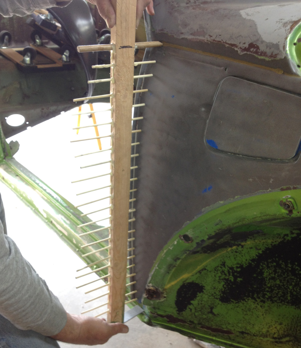
Looking at it along the ends of the bamboo skewers shows the nice curve:
Now we need to use that guide on the driver's side to pull the panel into position and shape.
Last edited by Baxsie on Fri Aug 08, 2014 12:21 pm; edited 1 time in total |
|
| Back to top |
|
|
Baxsie
Joined: 12 Apr 2012
Posts: 253
|
| Posted: Mon May 13, 2013 9:16 pm Post subject: |
|
|
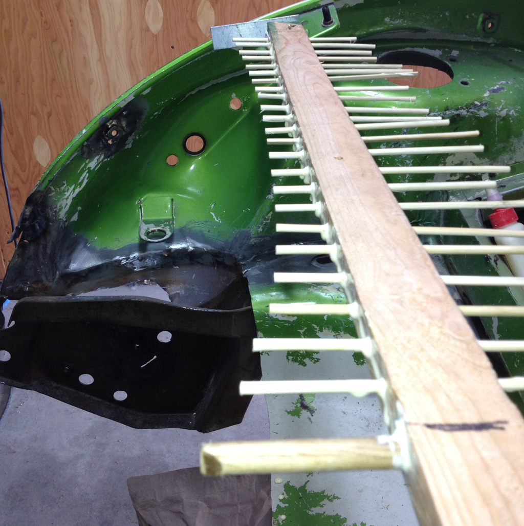
Here are before and after shots of the guide against the driver's (dented) side panel:

If you look closely, there is near 1/2" gap on the before side. The after side is fairly even. Well, better than when we started in any case.
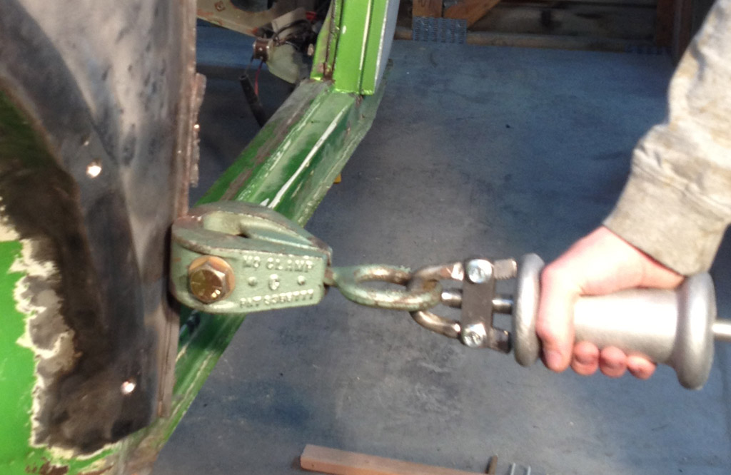
We pulled the seam by using a "MO" clamp from e-bay rigged to a HF slide hammer:
Looking down the panel, it is much better than before:

Last edited by Baxsie on Fri Aug 08, 2014 12:22 pm; edited 1 time in total |
|
| Back to top |
|
|
Baxsie
Joined: 12 Apr 2012
Posts: 253
|
| Posted: Tue May 14, 2013 7:57 pm Post subject: Is this the right tin for a FI engine? |
|
|
We looked at the engine tin today that I have collected from some various sources.
For background, this 1975 Fuel Injected bug has a larger opening in the engine compartment, and correspondingly larger cylinder tins.
I have cylinder tins that look correct, but I am wondering about the tin that goes along the rearmost part of the engine compartment. The holes in it seem to line up, but the edge does not seem to line up with the cylinder tins.
The 1 & 2 (passenger) side does not look too bad:

but the 3&4 (driver) side is a pretty darn big hole:

Can you confirm that the rear tin I have is right or wrong for a 1975 Fuel injected body?
Last edited by Baxsie on Fri Aug 08, 2014 12:22 pm; edited 1 time in total |
|
| Back to top |
|
|
Baxsie
Joined: 12 Apr 2012
Posts: 253
|
| Posted: Wed May 15, 2013 9:29 pm Post subject: |
|
|
Ugh. shoulda searched first and posted later:

It looks like this tin extends beyond the holes as it should for a FI.
Last edited by Baxsie on Fri Aug 08, 2014 12:23 pm; edited 1 time in total |
|
| Back to top |
|
|
Baxsie
Joined: 12 Apr 2012
Posts: 253
|
| Posted: Mon May 20, 2013 8:31 pm Post subject: |
|
|
Following the body+paint guy's advice, we got going on the paint removal. 80grit with the DA on the big sections. Detail work with the bead blaster:

I never like those goofy-looking visors. Now I have a legitimate reason to hate them:

Baby steps.
Last edited by Baxsie on Fri Aug 08, 2014 12:23 pm; edited 1 time in total |
|
| Back to top |
|
|
|