| View previous topic :: View next topic |
| Author |
Message |
Baxsie
Joined: 12 Apr 2012
Posts: 253
|
 Posted: Sun Mar 30, 2014 9:02 am Post subject: Right Rear Rust Repair (Foam of Death?) Posted: Sun Mar 30, 2014 9:02 am Post subject: Right Rear Rust Repair (Foam of Death?) |
 |
|
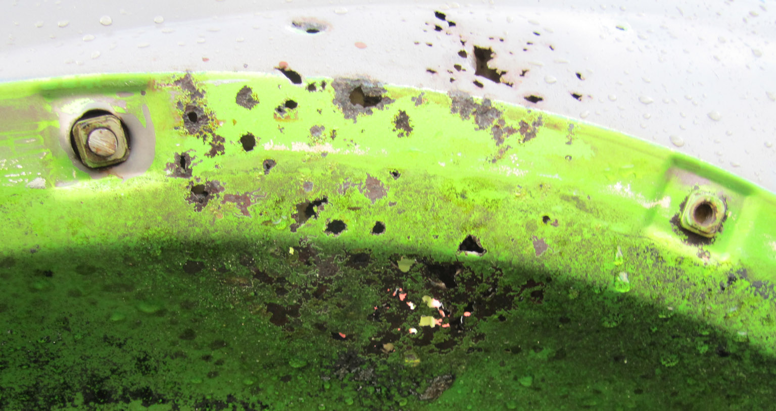
For a long time, we have known that this car had the dreaded (foam of death) rust in the right rear quarter. Here is a pic just after the initial pressure washing:
We marked what we thought was a good margin around the rusty area, and used the cut-off disk to remove it:

The metal there is in such sad condition. Depressing really. We had already removed much of the death foam from this area, removing this panel exposed even more stubborn bits:

We had some donor quarters from a 1968 that was destined for the crusher. They are factory fresh inside, clean primer, no rust at all. And yes, they also have the foam, but it is the kind that tears like good french bread, not the crunchy kind. No rust even where the foam was in direct contact. So at this point, I think the kind of foam the factory installed is much more important than whether there is foam at all. Or maybe the donor car lived its life in the desert:

After triming, the panel fit nicely:

Here is where we discovered a bit of a problem. Even though we cut all the perforations out, the metal where we welded in the patch was still very thin, and tended to blow out badly, or get punctured by the body hammer. So we ended up with a lot of small weld patches, and the attendant warpage. In the end, I think it will be OK and the body filler is not at all thick, but If I had to do it over I would have gone for a significantly larger patch:

Inside the fender well, we transitioned to a lap seam, welded font and back:

Last edited by Baxsie on Fri Aug 08, 2014 11:44 am; edited 1 time in total |
|
| Back to top |
|
 |
Baxsie
Joined: 12 Apr 2012
Posts: 253
|
| Posted: Sun Mar 30, 2014 9:21 am Post subject: Left front quarter panel seam repair near front door |
|
|
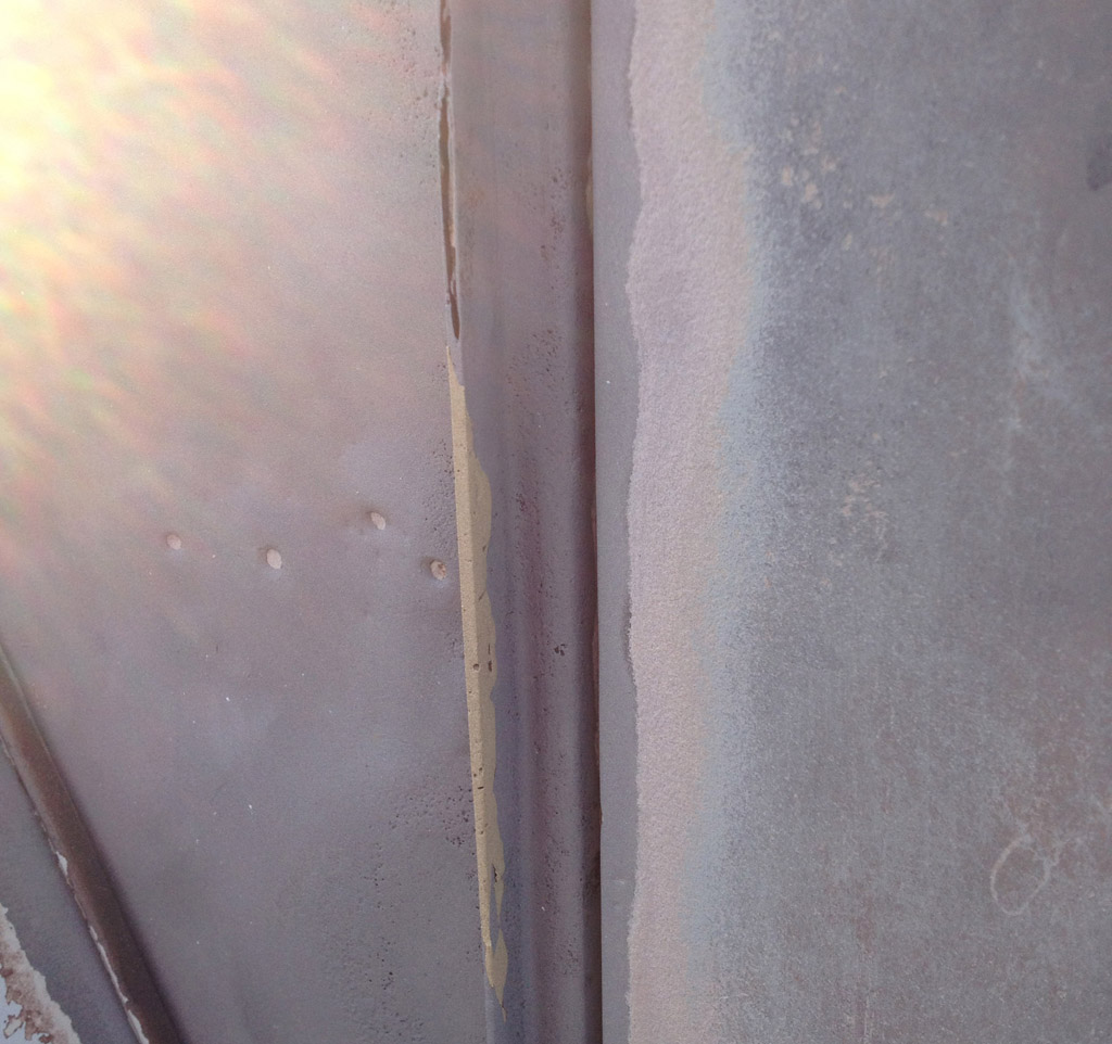
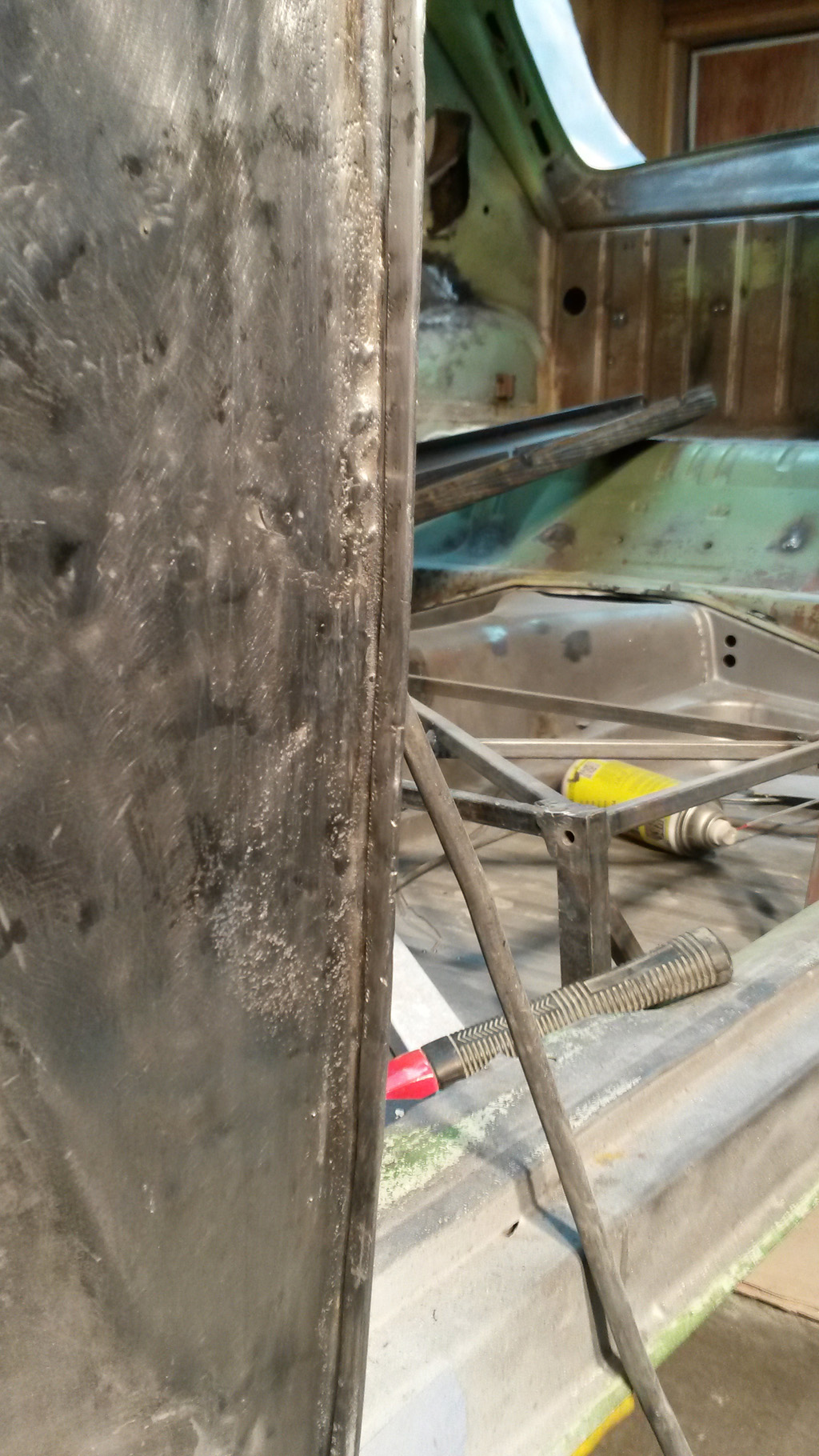
The front quarter panel had suffered some collision in its history, and then perhaps suffered more as that damage was repaired. They had pulled the panel with one of those screw puller things, so the panel was perforated at many points. The original seam had been repaired with some brazing:
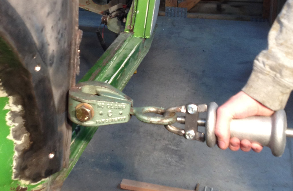
The trouble with this old repair was that the entire panel (and door post?) had been pressed in and then the panel had been brought out with a thick layer of bondo. This made the seam much shorter than it should have been. Some time ago we pulled the front quarter panel back to the original profile using the seam as a clamping point. This worked OK, but did more damage to the seam:
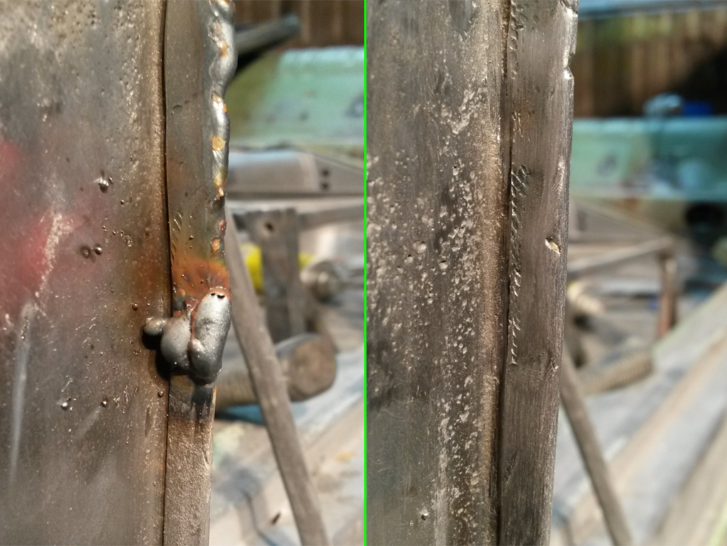
We cut a small strip of metal, clamped it in place and welded:
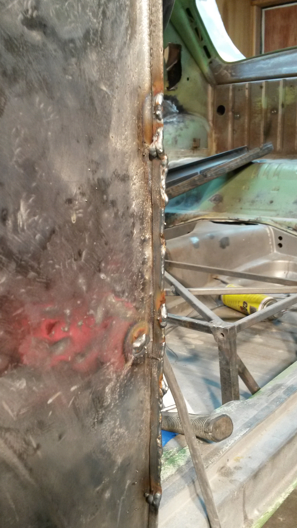
Then ground and sanded:
Here is a closer shot of the lower joint:
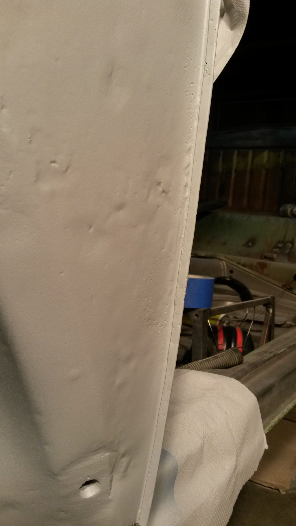
We then shot the bare metal with 2K epoxy primer, ready for sandable primer and filler as needed:
Last edited by Baxsie on Fri Aug 08, 2014 11:44 am; edited 1 time in total |
|
| Back to top |
|
|
Bad Bug Two

Joined: 23 Feb 2007
Posts: 94
Location: Spokane, WA
|
| Posted: Mon Mar 31, 2014 5:02 am Post subject: |
|
|
| Baxsie wrote: | Oh.
I'd love to get it on a dyno. Is there a dyno here in Spokane? |
There are a few.
| Quote: | | There was one out on Barker road, but I am not sure if they are still around. |
Phil Shelley. Great guy for old school muscle cars, but not too sure how he does with EFI and I do not believe that he has an eddy current brake on his dyno. I am pretty sure that he can only do inertia pulls. You need to be able to steady state tune to truly make the dyno session worth while.
| Quote: | | To get it "perfect" we could take it to a Seattle area dyno and have Mario from TheDubShop meet us there for a professional tune. |
I don't know Mario, but I have heard of him. With that being said, I have no doubt that he can do you a really good job. But for about the same price, I can teach you to tune your car and since it appears you guys like to do your own stuff, it might prove very worth while. Especially if you need or want to change the tune. (Sorry if this turned into an advertisement! Just trying to help out a fellow VW brother.)
http://spokane.craigslist.org/aos/4410027603.html
Also, here is a video of me doing a pull with my race bug on the dyno. I am running EFI on it and two stages of nitrous that are controlled by the ECU. I did all of the tuning at the college...
http://www.youtube.com/watch?v=rc8zP8Cykv4

_________________
Jeff Rogers
www.badbugracing.com
9.35 @ 145 |
|
| Back to top |
|
|
Baxsie
Joined: 12 Apr 2012
Posts: 253
|
| Posted: Sun Apr 13, 2014 7:28 pm Post subject: Repairing Stress Cracks in Sheet Metal Cooling Tin |
|
|
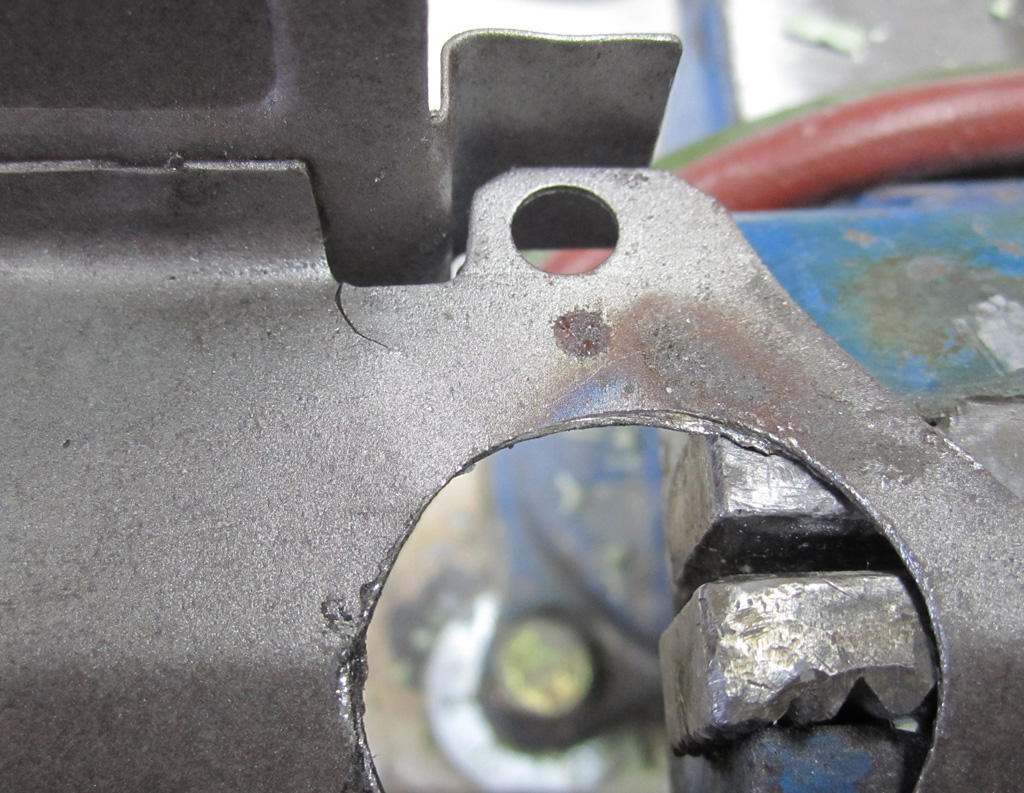
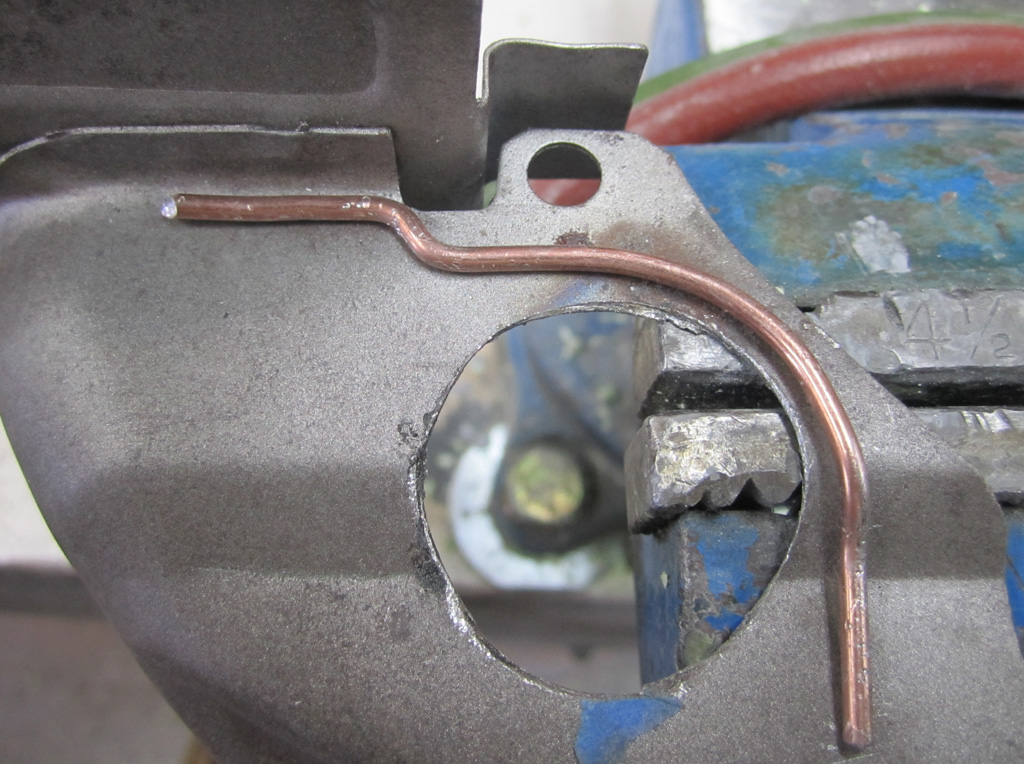
The piece of tin that sits in front of the pulley had some small cracks in it. On top of that, we added a hole in it for the crank trigger sensor, which further weakened it:
We formed a welding rod to be reinforcement:
My son brazed it into place, then we bead blasted:
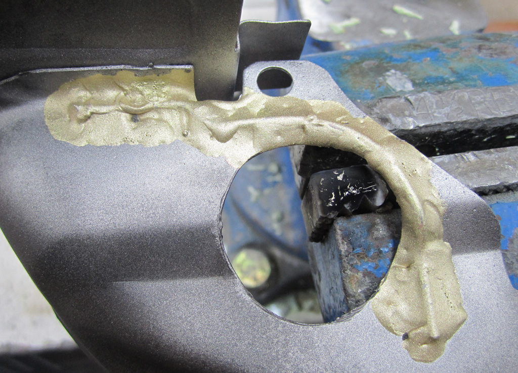
Hopefully that will stop any future cracking.
Last edited by Baxsie on Fri Aug 08, 2014 11:43 am; edited 2 times in total |
|
| Back to top |
|
|
Baxsie
Joined: 12 Apr 2012
Posts: 253
|
| Posted: Sat Apr 19, 2014 2:35 pm Post subject: Smoothing Interior Exhaust Welds at Flanges |
|
|
We tacked the tailpipe to the muffler:
And tacked a brace between the flange at the head and the muffler:
Then my neighbor welded them up nice:
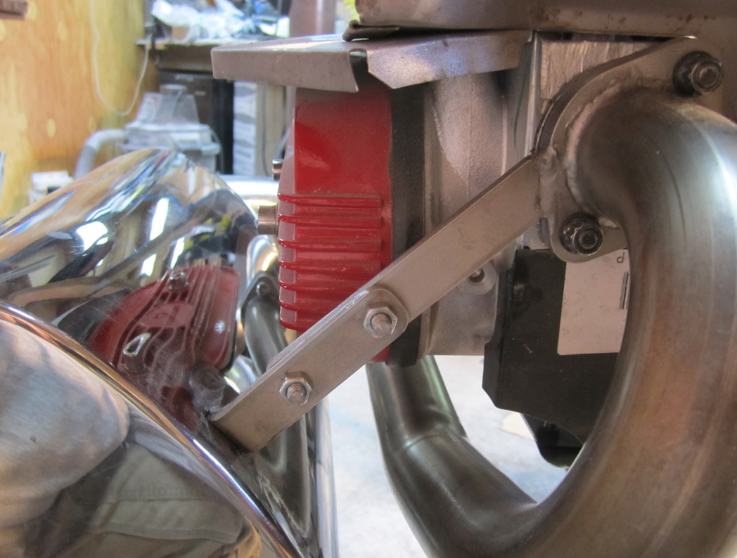
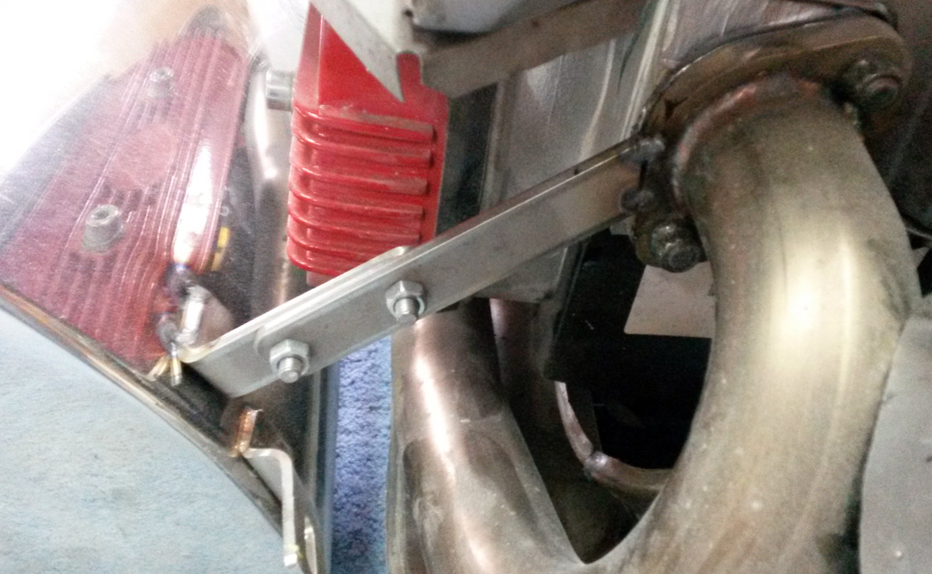
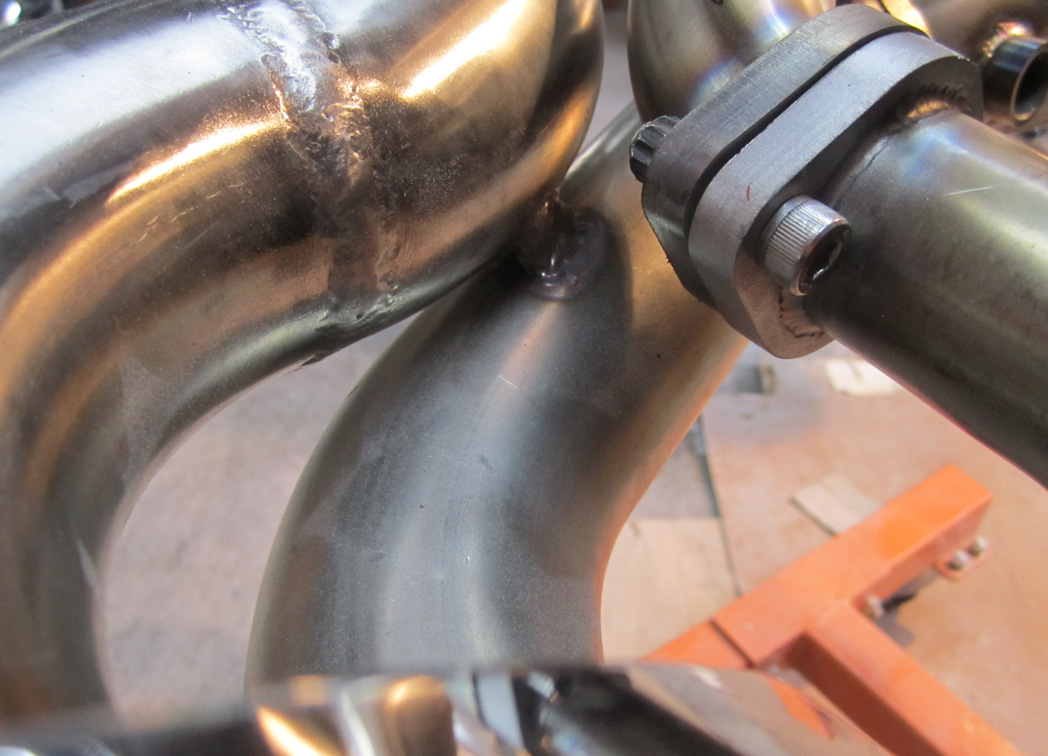
The tailpipe loops around very close to the collector, so we welded a brace between them so they would not rattle:
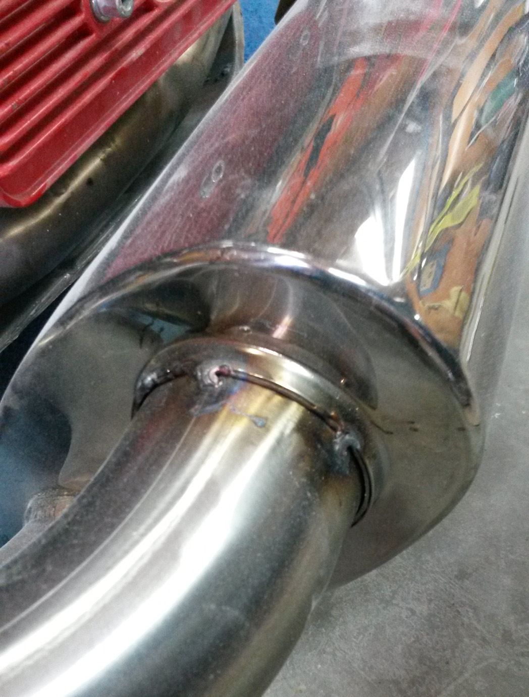
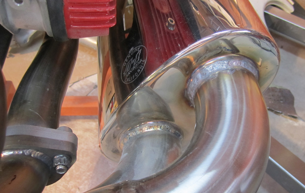
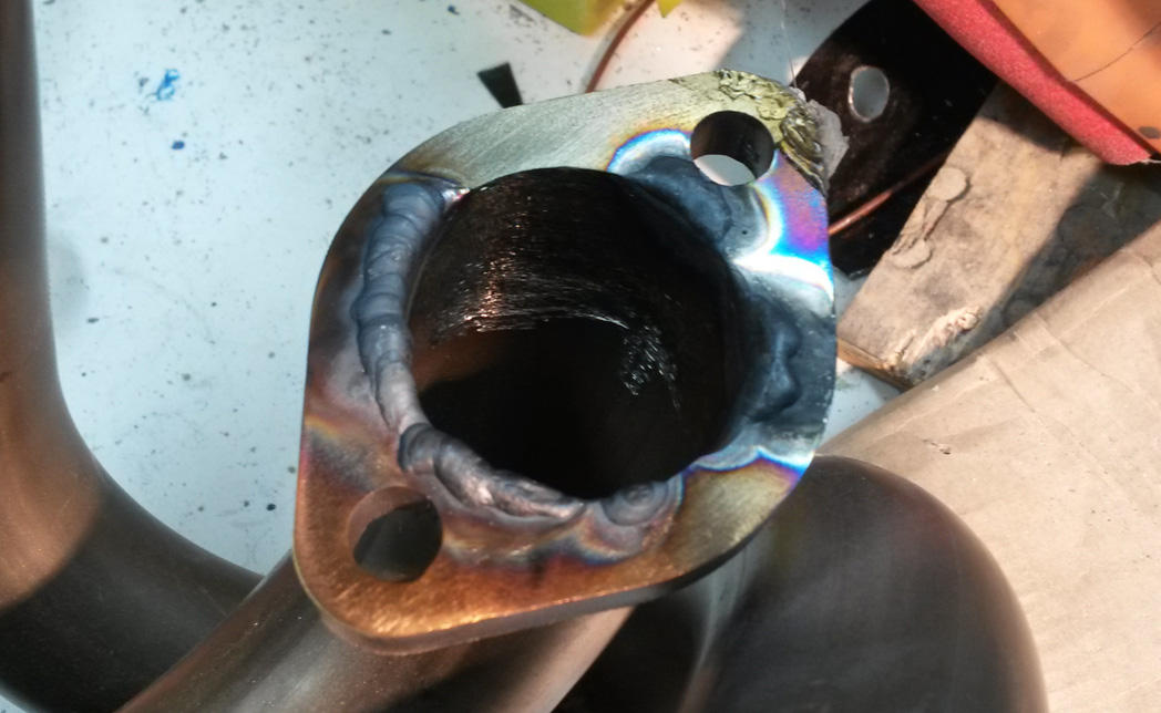
Where the stainless steel pipe is welded into the flanges, there is some incontinuity:
We decided to use the TIG and stainless rod to fill that in. This is a picture of the second pass at the welding, the first has already been ground down:
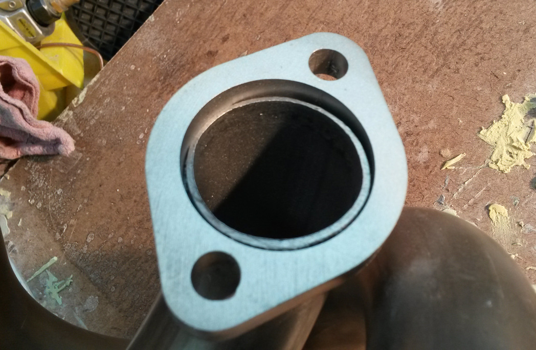
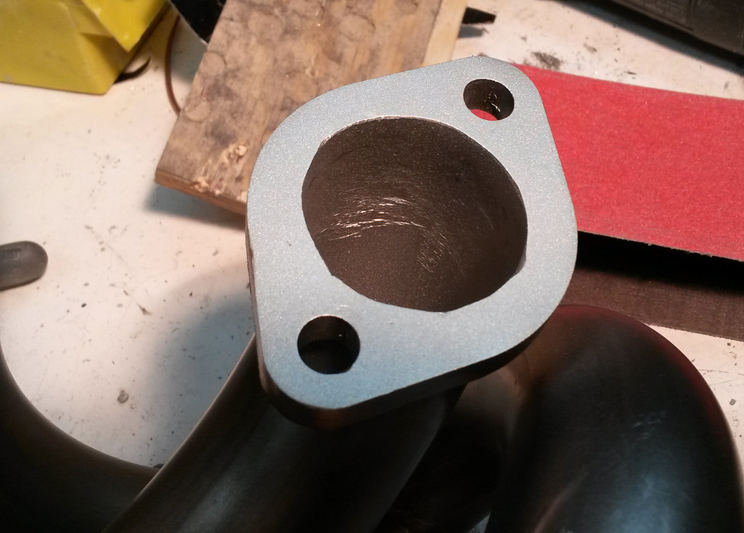
We used a burr on a die grinder to smooth the welds inside the pipe, and a belt sander to flatten the flange. Then a quick bead blast:
Last edited by Baxsie on Fri Aug 08, 2014 11:42 am; edited 1 time in total |
|
| Back to top |
|
|
Doodoob
Joined: 06 Jul 2011
Posts: 98
Location: Spokane, WA
|
| Posted: Sun Apr 20, 2014 7:23 am Post subject: |
|
|
| Cant wait to see you all cruising around! Looking good. |
|
| Back to top |
|
|
Baxsie
Joined: 12 Apr 2012
Posts: 253
|
| Posted: Mon Apr 21, 2014 8:24 pm Post subject: Mounting Sanden Scroll Air Conditioner Compressor |
|
|
We are trying to come up with a good way to mount the Sanden Scroll Air Conditioner compressor. About the only good, beefy mounts available are the generator stand studs. The front set of studs already has the MST belt tensioner under it.
Our plan is to make a bracket out of aluminum, generally simple shapes cut to fit together then welded.
We made a CAD model of the parts:
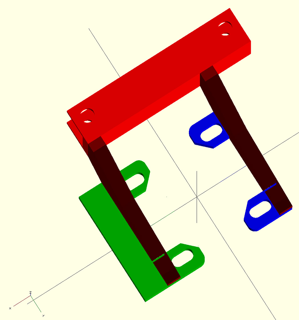
The green part represents the base of the MST tensioner bracket. The blue piece is a mirror of that bracket created to go on the front generator stand studs.
The bright red part is a "C" channel that will fit over two of the compressor's mounting bosses.
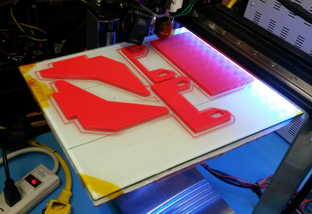
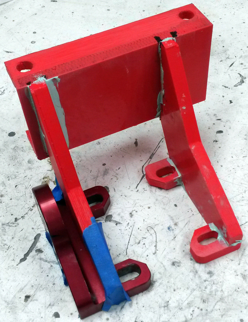
For prototyping, we printed plastic parts using PLA on the company's MakerGear M2 printer:
A quick mock-up of how the parts would go together:
Here is the way the belt would be routed, and the position of the compressor. The blue is tape used to hold the plastic parts in position:
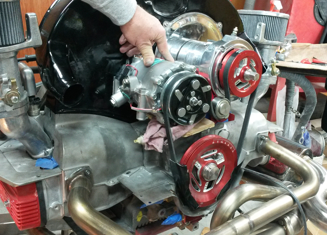
The prototye let us find out that the bracket cannot be completely welded and then installed, there is no way to get it around the generator stand. So we will come up with a 2-piece design, and give that a try.
Our hope is that the beefy aluminum will be strong enough. After some practice welds on aluminum, I think we will want to hire out the welding to a pro.
If the bracket is not strong enough, we may have to grab the mounting ears on the other side and bring some strut down to the case. Maybe the distributor clamp stud. Not much in that area.
Last edited by Baxsie on Fri Aug 08, 2014 11:42 am; edited 1 time in total |
|
| Back to top |
|
|
Baxsie
Joined: 12 Apr 2012
Posts: 253
|
| Posted: Thu Apr 24, 2014 9:11 am Post subject: Mount for Sanden AC Compressor, take 2 |
|
|
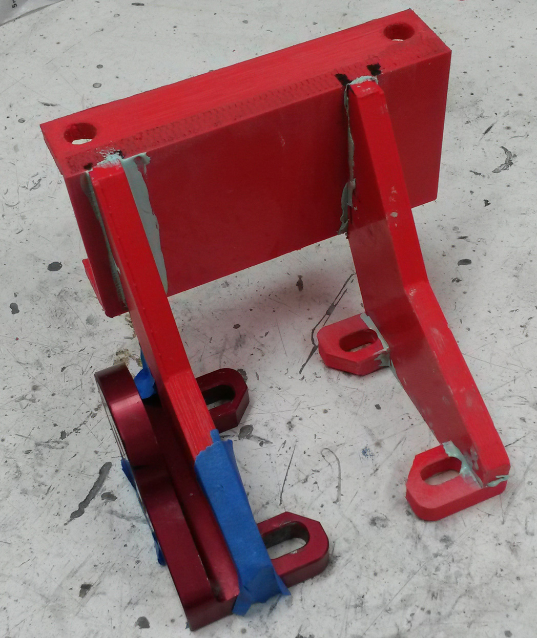
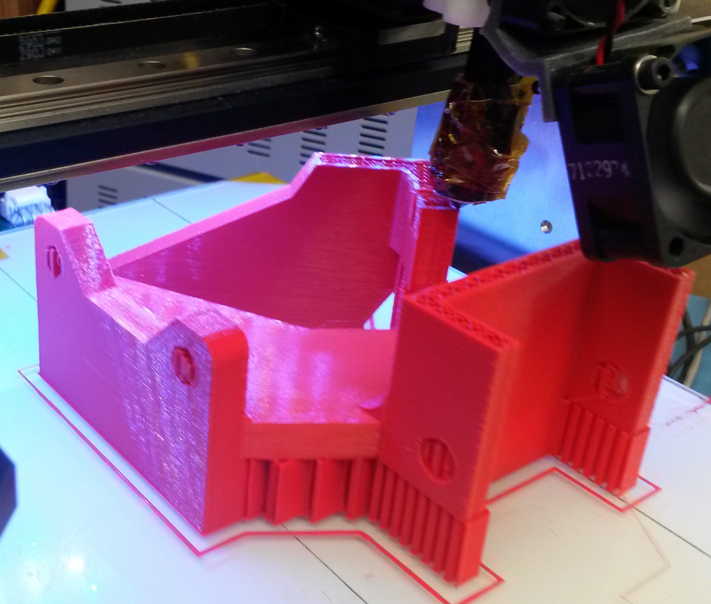
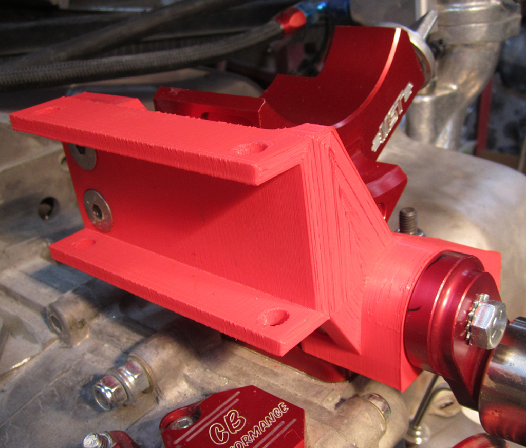
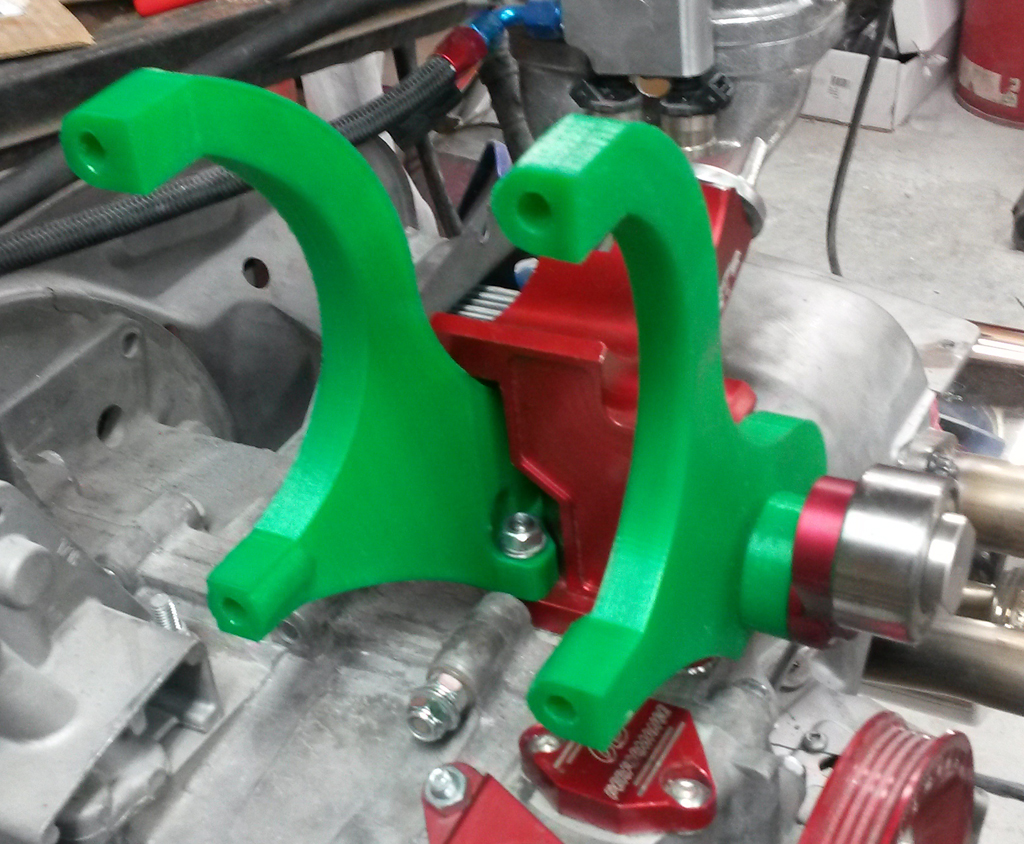
Went back to the drawing board and fixed up the design. Rather than several flat parts cut to interlock and be welded, we decided to go with a 2-piece CNC design. We used the MakerGear M2 to print out the prototype in red PLA:
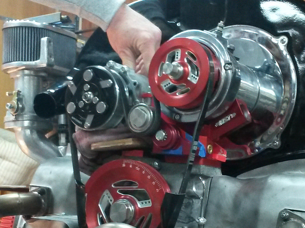
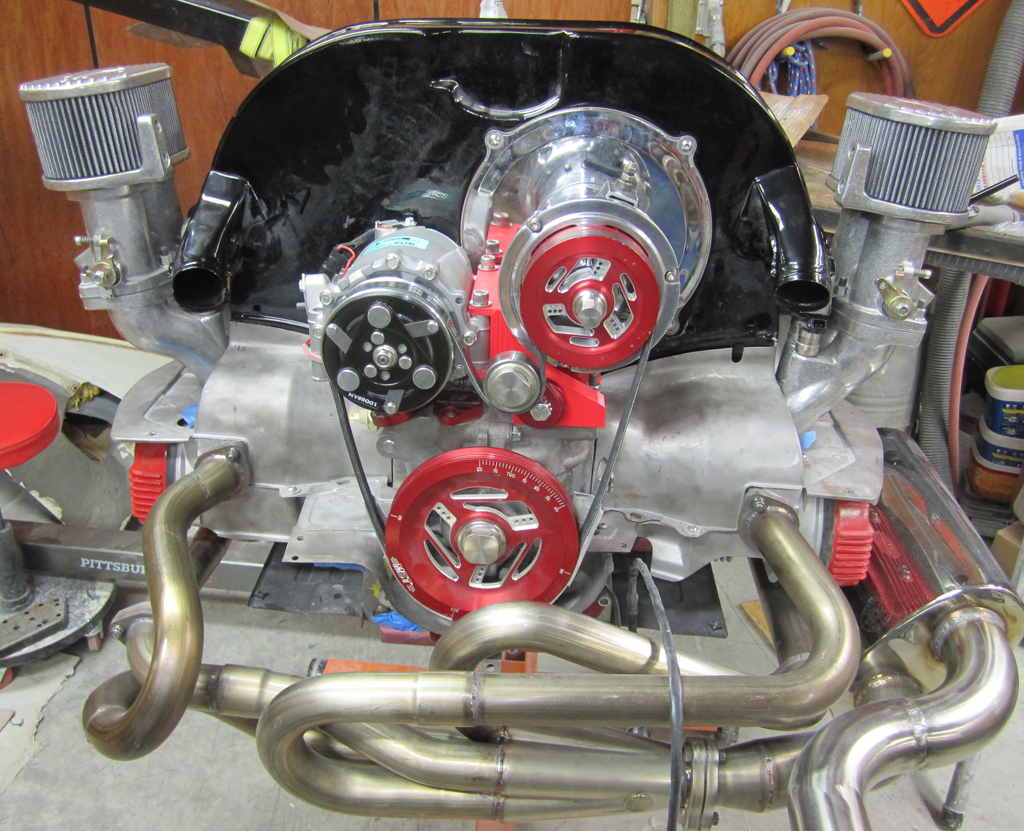
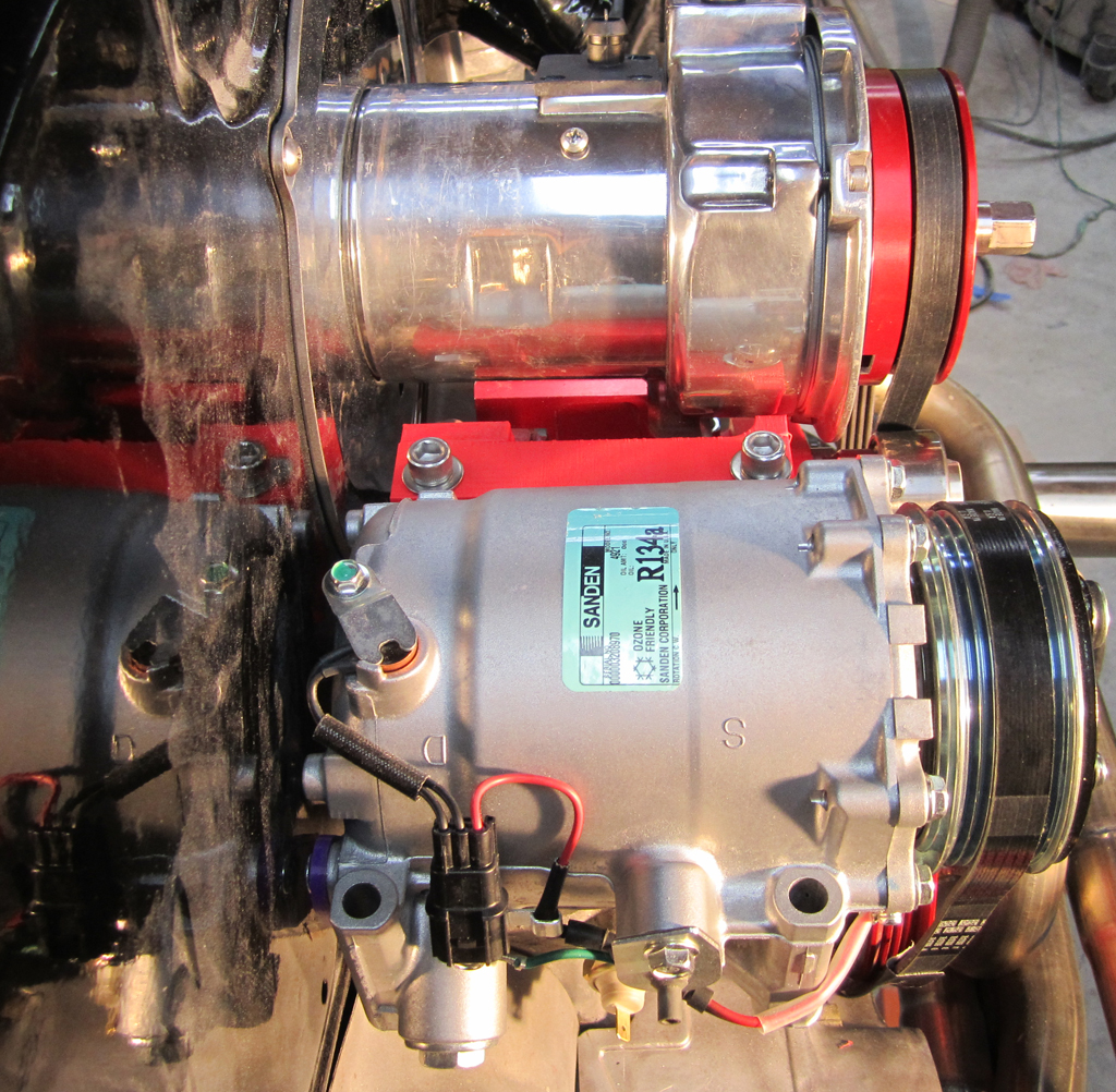
Here is the prototype mounted to the block, still don't have the correct length studs:
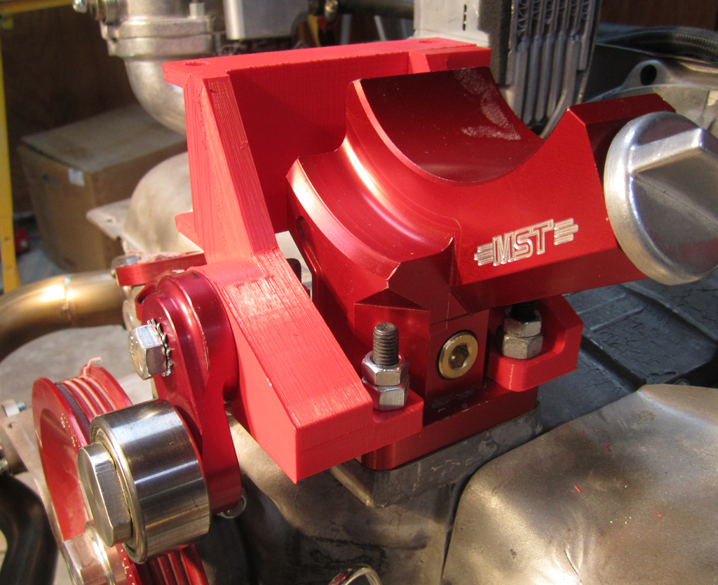
The plastic model is not particularly strong, and the compressor weighs 15 pounds, so I was not sure if it would hold the weight. Surprisingly, the plastic held up very well:
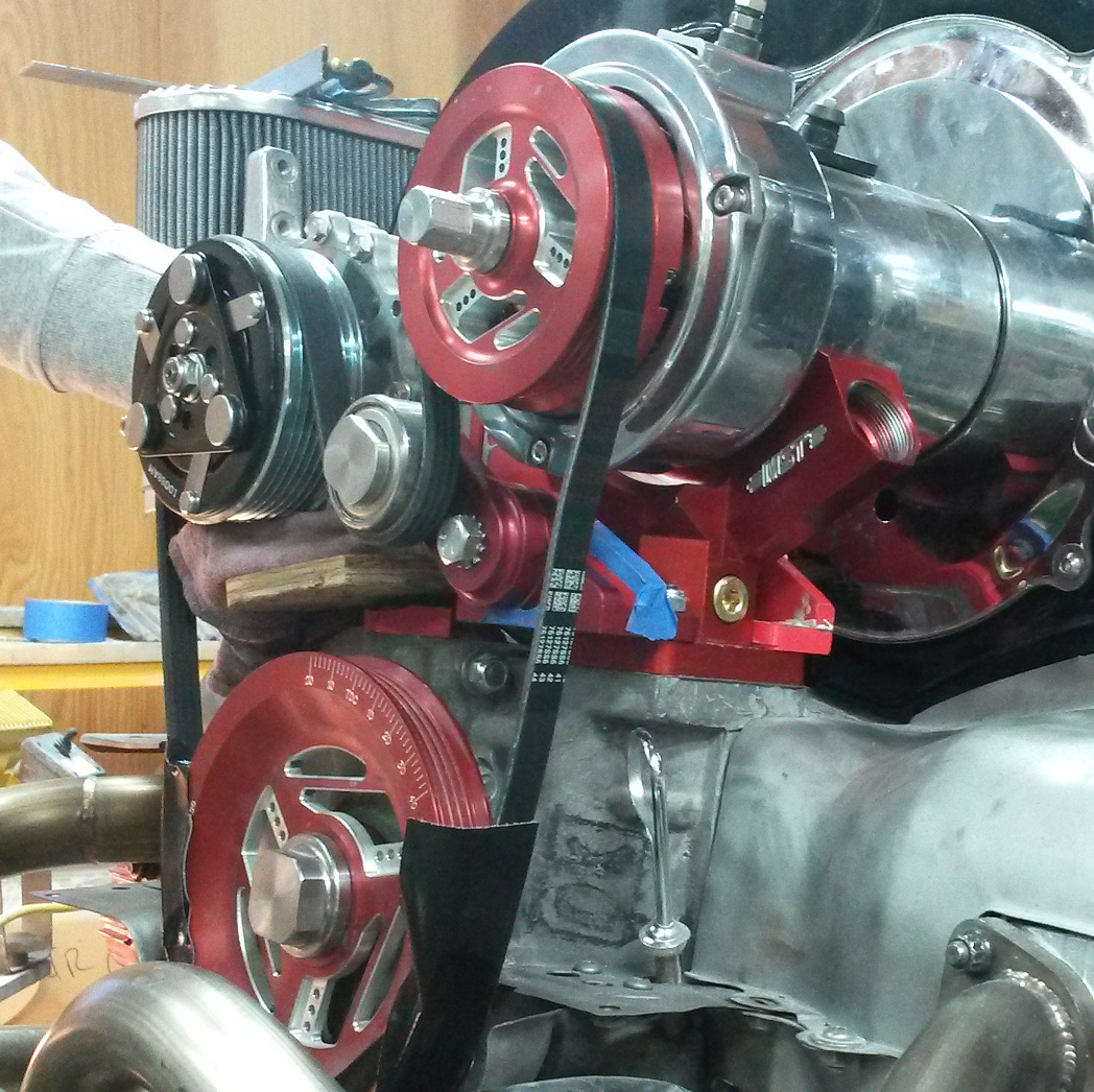
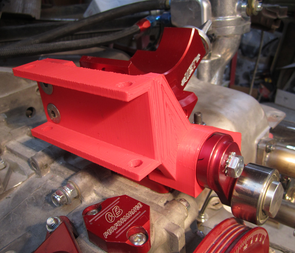
Part of what allows this to work is not having a distibutor or mechanical fuel pump. I'm working with TheDubShop on getting an early version of their MiniCamSync. In theory it would fit in there:
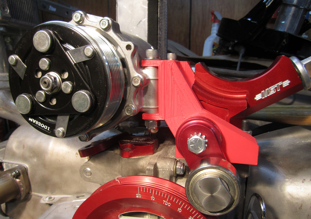
The alignment looks good, with the belt one notch back on the compressor pulley.
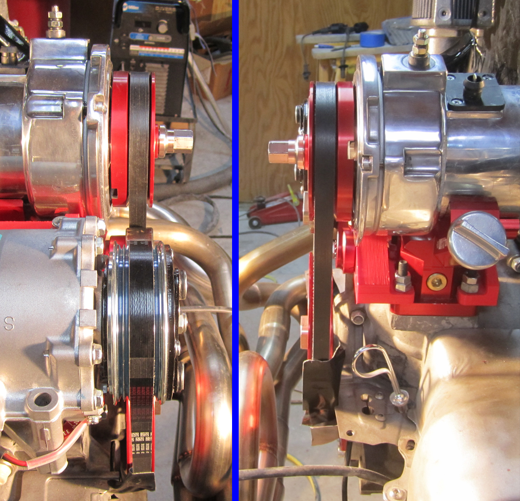
There is some clearance between the fan shroud and the compressor:
Next up will be trying to find a CNC shop that can make it for a reasonable price.
Last edited by Baxsie on Fri Aug 08, 2014 11:41 am; edited 1 time in total |
|
| Back to top |
|
|
Baxsie
Joined: 12 Apr 2012
Posts: 253
|
| Posted: Sat Apr 26, 2014 8:11 pm Post subject: Air Conditioner Compressor: Now in the correct orientation |
|
|
I started to wonder if the orientation of the AC compressor was critical.
I was not able to find a definitive answer, but after poking around a bunch, I decided that we had better put the oil fill plug on the top!
Have a 3d model built:
The first of the new parts is printing now in fantastically sexy transparent green:
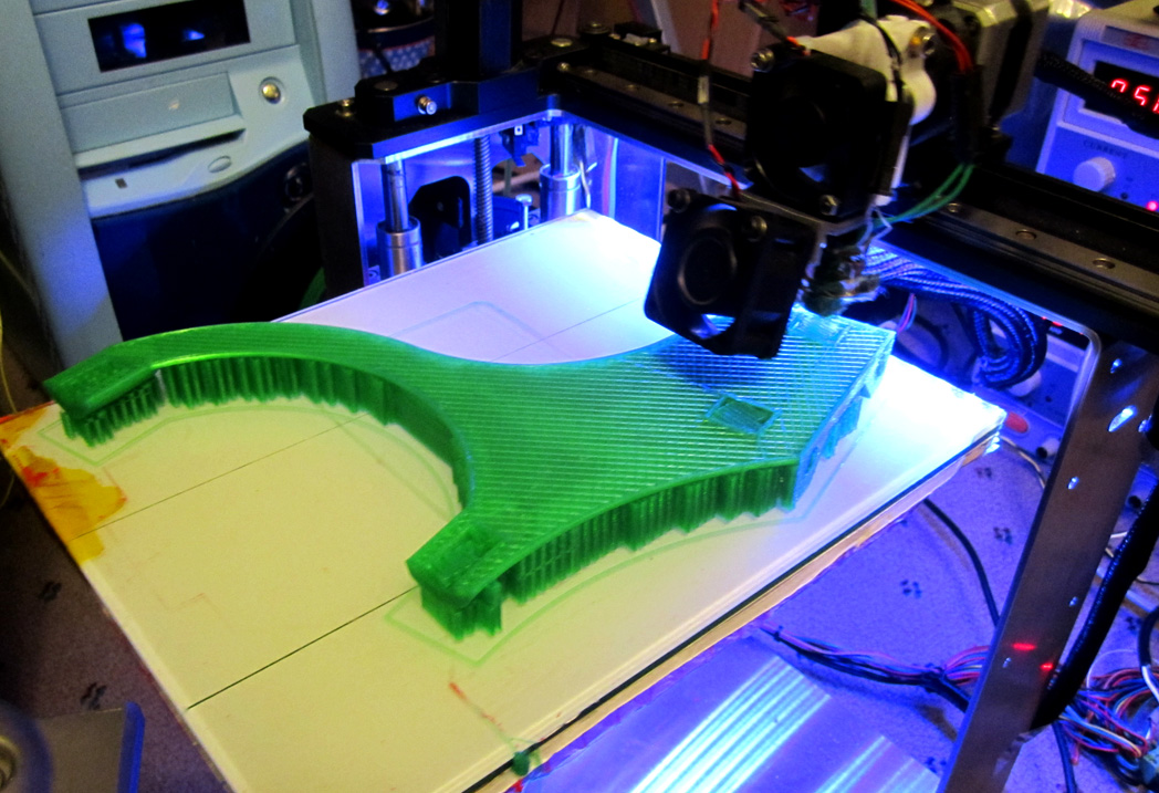
We will have to test fit these up and tweak them . . . then off to be machined from aluminum.
Last edited by Baxsie on Fri Aug 08, 2014 11:41 am; edited 1 time in total |
|
| Back to top |
|
|
project_dog
Joined: 21 Apr 2014
Posts: 33
|
| Posted: Sun Apr 27, 2014 12:44 am Post subject: |
|
|
| wow. Great work. Plus nice 3d printer. |
|
| Back to top |
|
|
Baxsie
Joined: 12 Apr 2012
Posts: 253
|
| Posted: Wed Apr 30, 2014 8:34 pm Post subject: Progression of 3d model for Compressor Mount Design |
|
|
| project_dog wrote: | | wow. Great work. Plus nice 3d printer. |
Thanks for the kind words. The printer is a MakerGear M2:
http://www.makergear.com/products/m-series-3d-printers
Good printer, good folks.
The first version was rather simple, intended to be laser or water-jet cut plates welded together. The big problem was that it could not be assembled around the alternator stand. D'Oh.
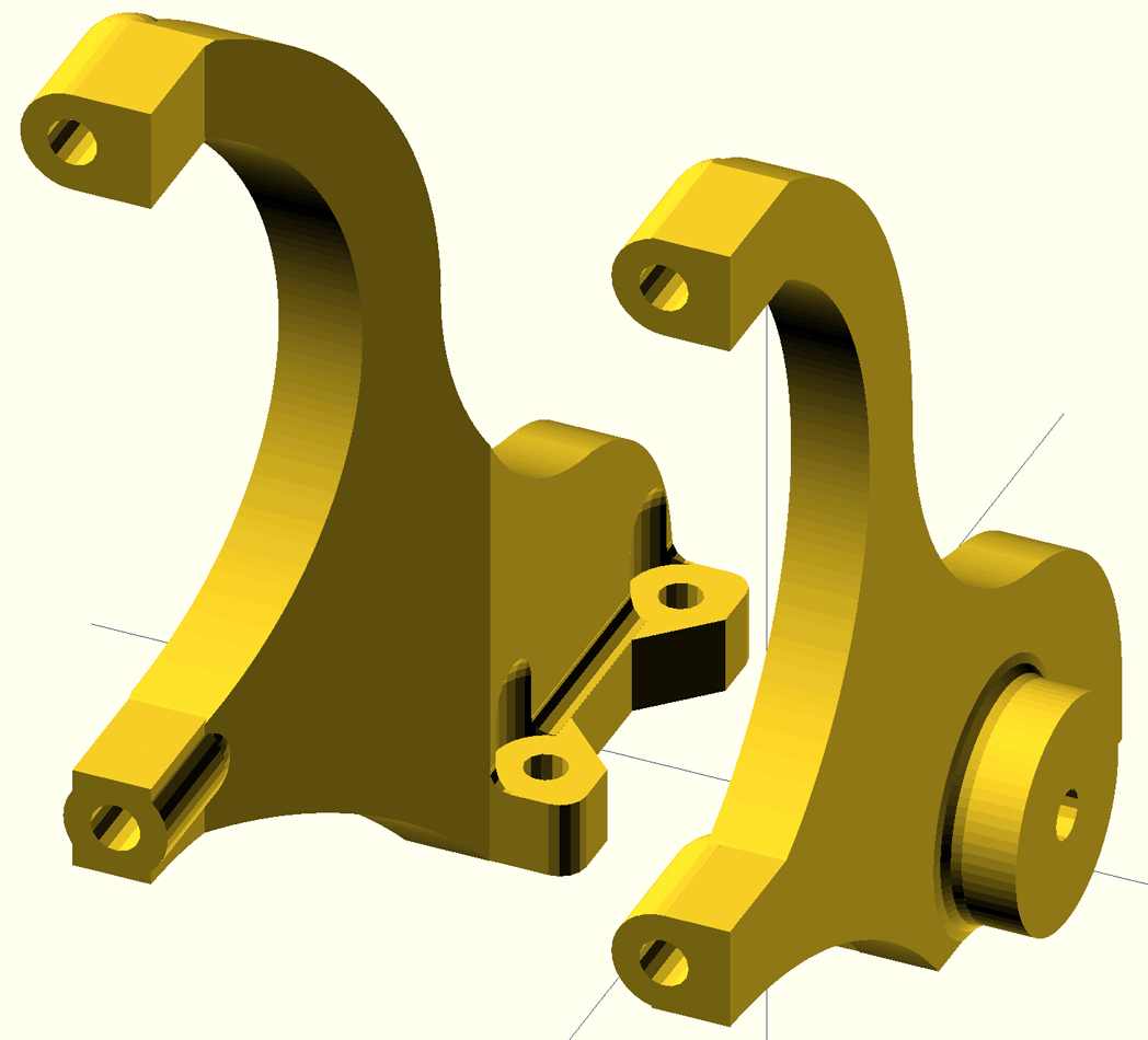
The next version was the same concept, but two pieces that bolted together, and designed to be CNC milled rather than welded:
Then we realized that the Sanden TRSE09's mounting orientation was hosed, since the oil fill port was aimed down. D'Oh. So we did the "logical" thing and rotated it 90 degrees. This put the oil fill port upward at least. At the same time I put a query in to Sanden to ask about orientation. This design puts the compressor at the same height as the alternator, and they are mirrored around the case split.
That version was two seperate, independent arms. They were beefy, but you could tell that the stability fore-aft was not good. The next version added a block to join them with bolts, but it never got off the desk:
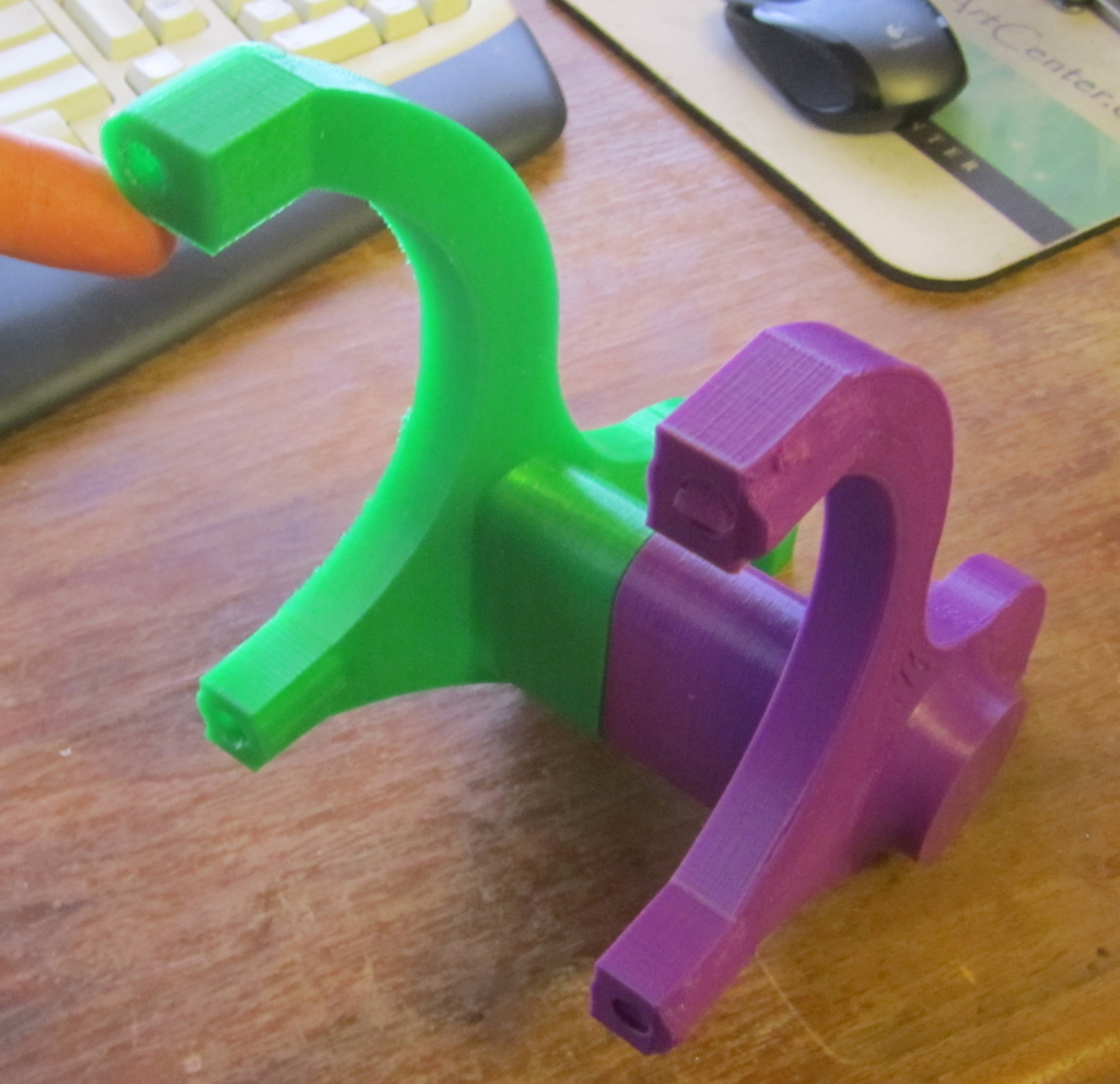
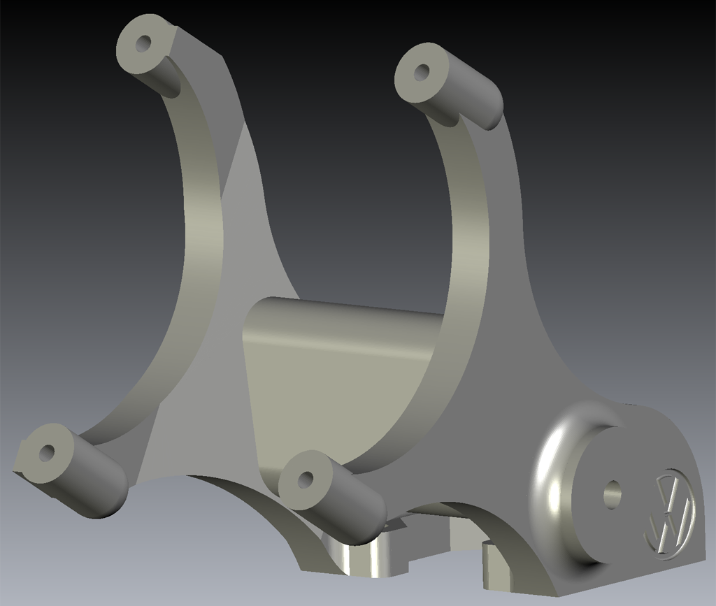
We got the information back from Sanden. They did supply me with a application drawing of the compressor, which was great since I was able to firm up all my measurements. Concerning the rotation though, I did not like their answer, so I decided to see how this compressor was mounted in its OEM application. I found this parts drawing:
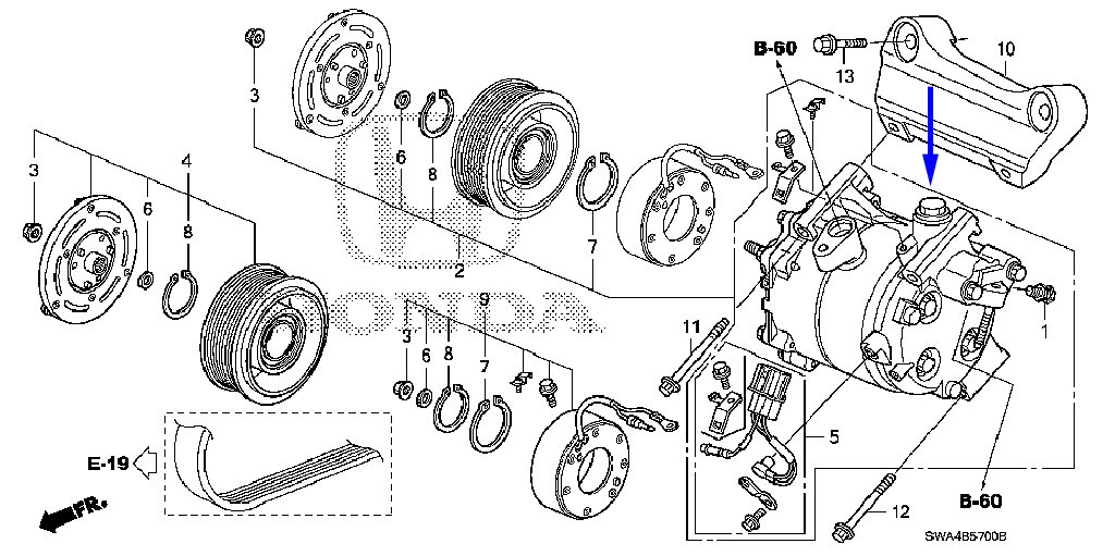
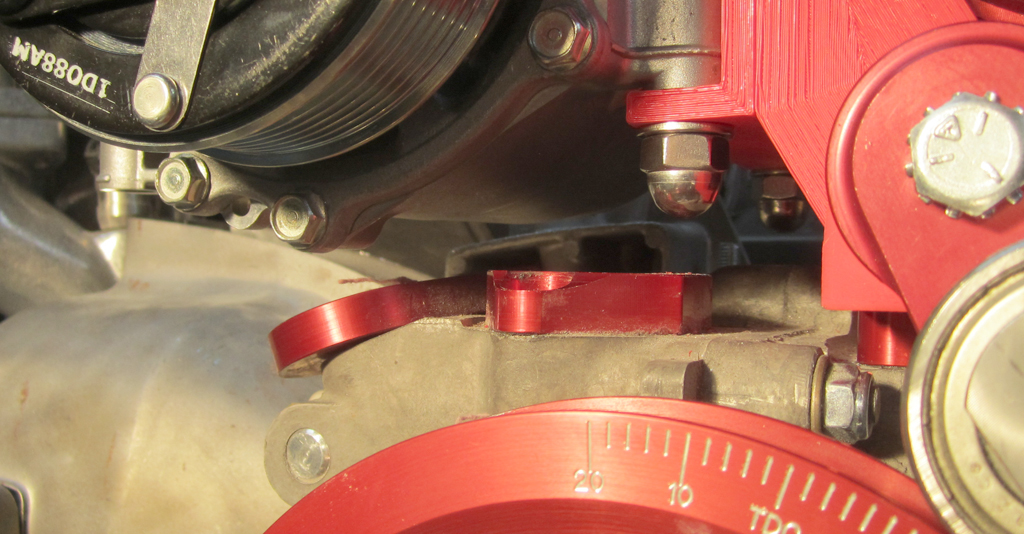
Which to me shows the oil fill port straight up and flat on the top. Going with that, the next version actually looks best of all, IMHO:
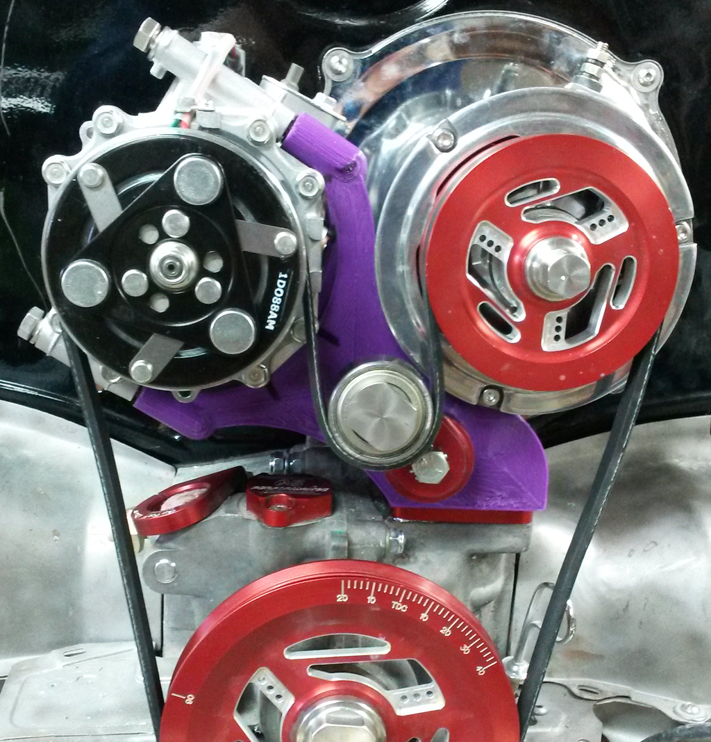
The rotation makes the arms shorter, which makes it lighter and more rigid.
A slightly longer belt will move the tensioner closer to flat, and bring it closer to the case center line.
This version still has the beefy-bolted-together cross bar that makes it very stable. I think the weakest point now will be the alternator stand mounting studs:
There are still some fiddly things to work out, a couple of minor clearances to knock out, but at this point I am feeling fairly confident that the design is settling down.
Last edited by Baxsie on Fri Aug 08, 2014 11:40 am; edited 1 time in total |
|
| Back to top |
|
|
project_dog
Joined: 21 Apr 2014
Posts: 33
|
| Posted: Wed Apr 30, 2014 11:21 pm Post subject: |
|
|
| what about your disturber? |
|
| Back to top |
|
|
Baxsie
Joined: 12 Apr 2012
Posts: 253
|
| Posted: Thu May 01, 2014 7:50 am Post subject: |
|
|
| project_dog wrote: | | what about your disturber? |
This motor uses a MegaSquirt MS3Pro:
http://thedubshop.goodsie.com/electronics
to control both the fuel injection and ignition timing. There is a timing wheel on the back of the crank pulley.
Where the distributor was, we will install a "Mini Cam Sync" from TheDubShop:
http://thedubshop.goodsie.com/mini-cam-sync
. . . provided it gets done in time. If not the we may have to go with a distributor plug an use wasted spark temporarily. |
|
| Back to top |
|
|
Bad Bug Two
Joined: 23 Feb 2007
Posts: 94
Location: Spokane, WA
|
| Posted: Fri May 09, 2014 4:21 pm Post subject: Re: Progression of 3d model for Compressor Mount Design |
|
|
| Baxsie wrote: | | I think the weakest point now will be the alternator stand mounting studs |
I think that there should be enough meat in the case that you could possibly put head stud inserts in to strenghten the case. Maybe even get higher grade studs? If there is enough room, maybe even larger diameter studs?
Looking great!
_________________
Jeff Rogers
www.badbugracing.com
9.35 @ 145 |
|
| Back to top |
|
|
Baxsie
Joined: 12 Apr 2012
Posts: 253
|
| Posted: Fri May 09, 2014 5:20 pm Post subject: Re: Progression of 3d model for Compressor Mount Design |
|
|
| Bad Bug Two wrote: | | Baxsie wrote: | | I think the weakest point now will be the alternator stand mounting studs |
I think that there should be enough meat in the case that you could possibly put head stud inserts in to strengthen the case. Maybe even get higher grade studs? If there is enough room, maybe even larger diameter studs?
Looking great!
|
Yes, I think all of those would be good approaches. For now I have longer studs (good grade) of the same diameter. I have them threaded into the case a fair distance. I used the one you can feel the under side of on the generator stand as my goal, with one thread showing past the bottom of the case hole. The others are screwed into the case the same amount.
If this setup breaks, then we would have to go back in with larger studs. But we will burn that bridge when we get to it -- I think this setup will be plenty strong. |
|
| Back to top |
|
|
|
|
You cannot post new topics in this forum
You cannot reply to topics in this forum
You cannot edit your posts in this forum
You cannot delete your posts in this forum
You cannot vote in polls in this forum
You cannot attach files in this forum
You can download files in this forum
|
|