| View previous topic :: View next topic |
| Author |
Message |
Baxsie
Joined: 12 Apr 2012
Posts: 253
|
 Posted: Sun Feb 16, 2014 7:28 pm Post subject: Super Beetle Rear Fenders Wider - Cutting & Welding Posted: Sun Feb 16, 2014 7:28 pm Post subject: Super Beetle Rear Fenders Wider - Cutting & Welding |
 |
|
After cutting the fenders, we adjusted the overlap and used sheet metal screws to hold them where we liked them. We then used some spray paint to mark where the top fender lays on the bottom fender:
From there, we marked out by the widthe of the flanging tool, and then trimmed and flanged the fender:
Here is a shot of some of the warly welding on the driver side:
We left the tail light area for the last. Here are the tabs welded, then smmoothed:
Some pounding to counteract the warpage, then more smoothing, and it is getting close to ready for the 2K primer:
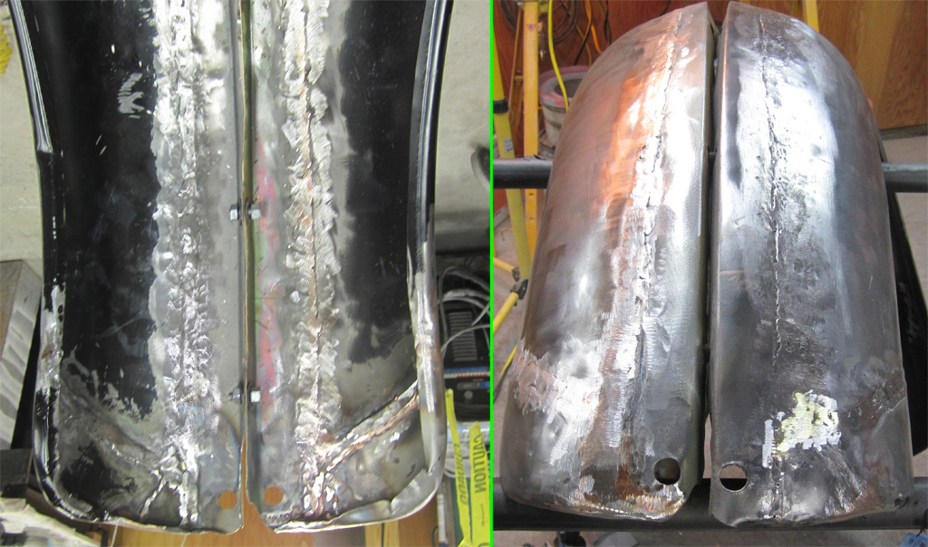
Ethan was back on the welding when we moved to the passenger side, so the welding is a bit nicer:
Considering that he did not know how to weld at all when this project started, he is knocking out some beautiful beads. And this is on the thin fender material:
Last edited by Baxsie on Fri Aug 08, 2014 11:49 am; edited 1 time in total |
|
| Back to top |
|
 |
Baxsie
Joined: 12 Apr 2012
Posts: 253
|
| Posted: Mon Feb 17, 2014 7:44 pm Post subject: Super Beetle Rear Fenders Wider - Shortening Front Part |
|
|
I was directed to a discussion on Silicon-Bronze MIG wire, so we held off the remainder of the welding on the passenger side in hopes that the silicon-bronze will do less warping.
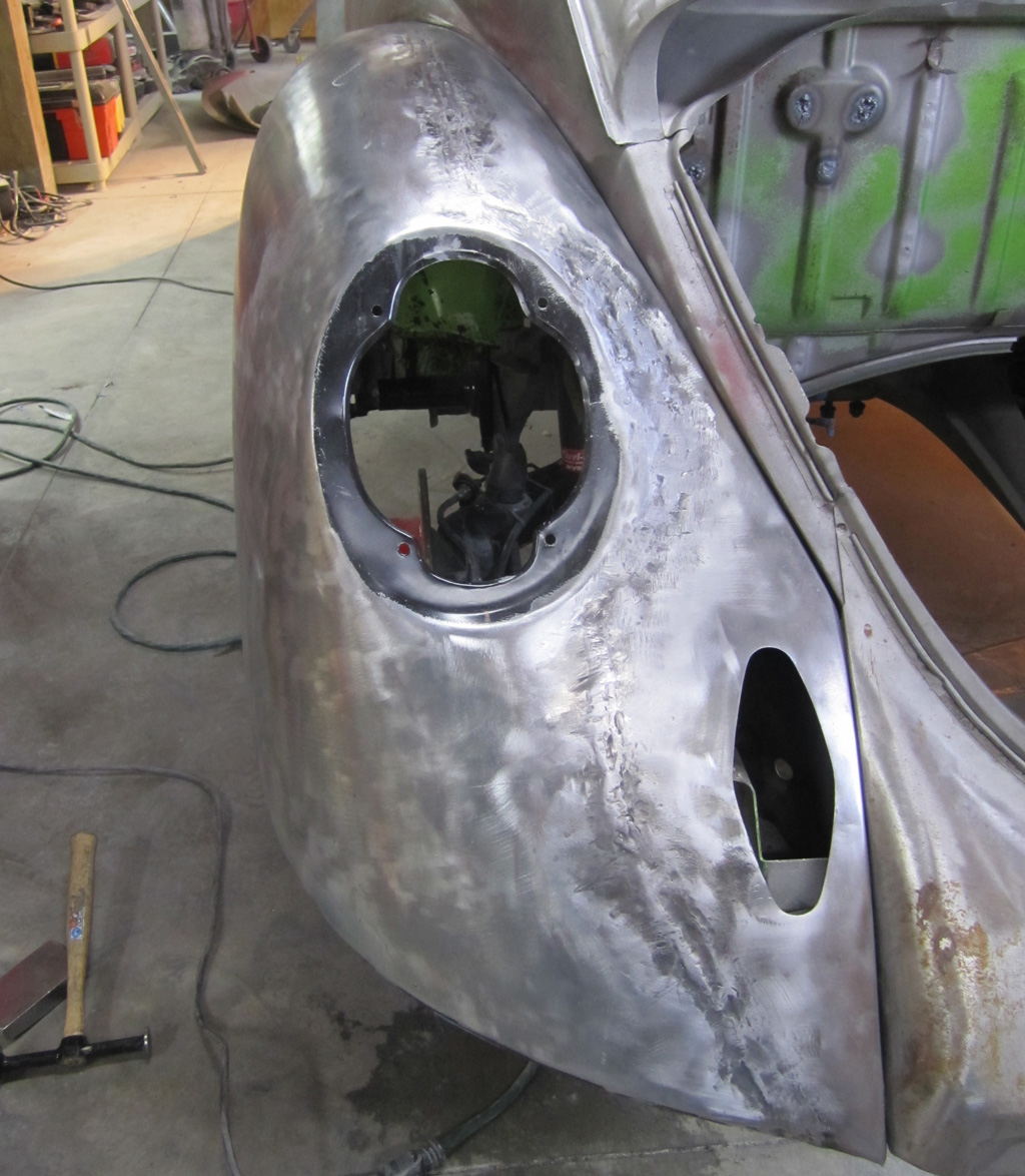
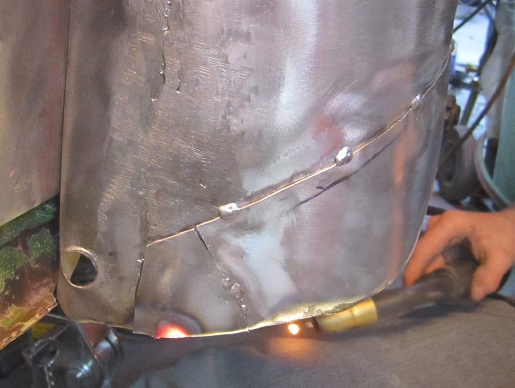
We did tackle shortening the front part of the drivers side rear fender. There is such a slope where the fender meets the body in that area that the fender moves moves down about as much as it moves out. Here is a pic of where we were cutting:
And here is the frankenstein patch job. We did not see why to make the under-cut which seems to weaken the fender right where it could use some strength for the running board. So it is now more rectangular:
Last edited by Baxsie on Fri Aug 08, 2014 11:48 am; edited 1 time in total |
|
| Back to top |
|
|
Baxsie
Joined: 12 Apr 2012
Posts: 253
|
| Posted: Mon Feb 17, 2014 7:48 pm Post subject: Fog lights in front fenders, DRL in bumper |
|
|
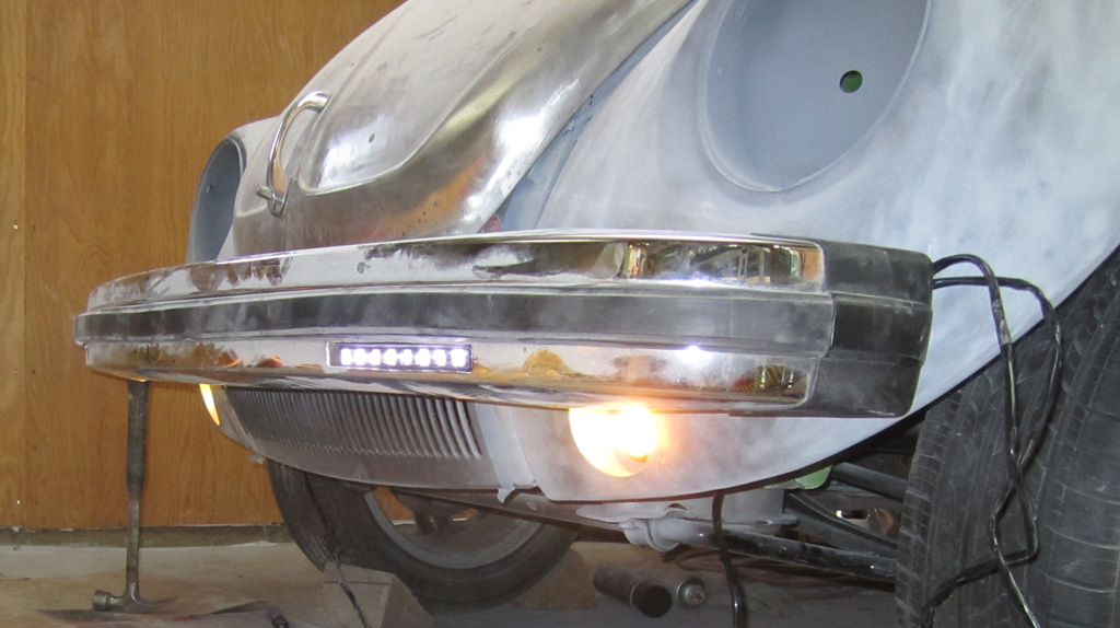
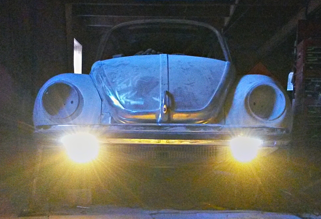
We installed the bumper to make sure there was not any problem with the fog light's position. Even if there was a problem, there is not much we would be willing to change at this point. In any case, the setup looks pretty good. It is intentional that the bumper "trims" the fog light slightly on the top. The cutoff is still due to the optics in the fog light, but the bumper does help trim some of the "overspray" light:
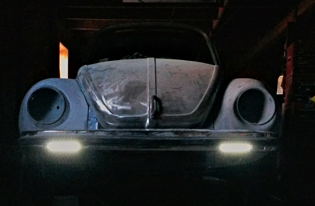
The cutoff of the Hella Micro DE fog lights is pretty sharp:

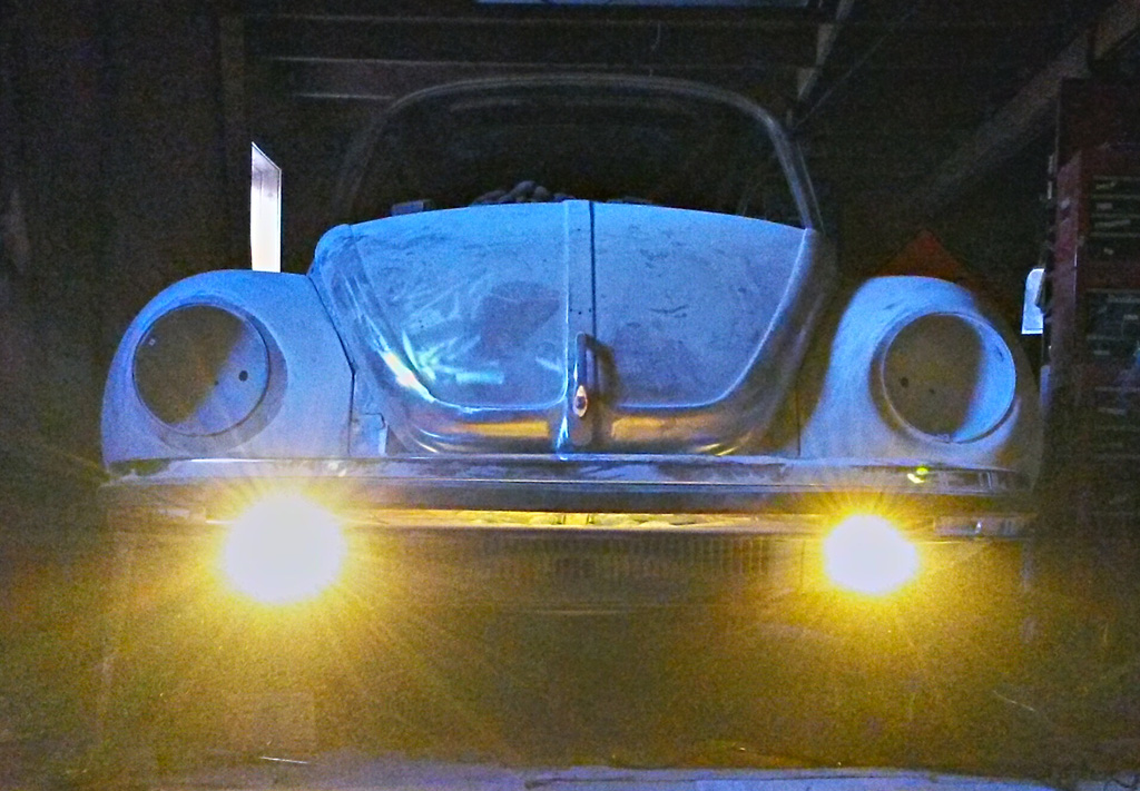
Here is a deer's-eye-view of the fog lights only on:
The LED DRL (Daytime Running Lights) only:
And, just for kicks, both the fog and DRL on:
Last edited by Baxsie on Fri Aug 08, 2014 11:48 am; edited 1 time in total |
|
| Back to top |
|
|
Baxsie
Joined: 12 Apr 2012
Posts: 253
|
| Posted: Sun Mar 02, 2014 10:27 am Post subject: 1975 Super Beetle Rear Fenders Wider |
|
|
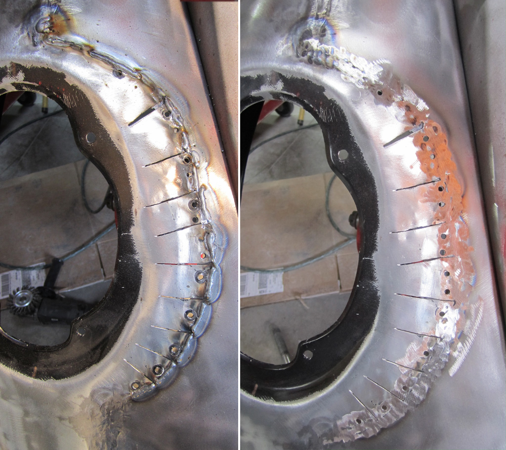
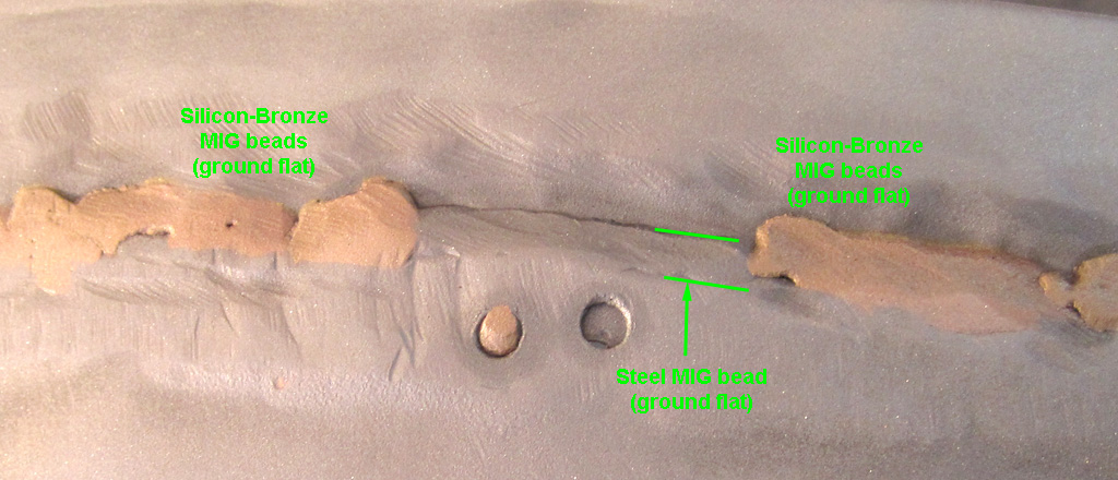
We got some silicon-bronze MIG welding wire. It is very interesting. Can't say it is better or worse than the steel wire at this point. Certainly different. It looks like a brazed seam, with lots of copper color. Here is steel weld sandwitched between the silicon-bronze beads, after rough grinding and bead blasting. Not sure if the warping is better or worse--we were getting "pretty good" at welding with the steel 0.023 MIG wire, but are back to being beginners at this 0.030 Silicon Bronze wire:
We continued with shortening the front part of the other rear fender. We mounted them to each other to make sure they matched--this also made them easier to handle and less floppy.
These look pretty rough. We will do more metal work to get them closer to where they need to be:
Mounted up agin to check for symmerty and some more hammer work:
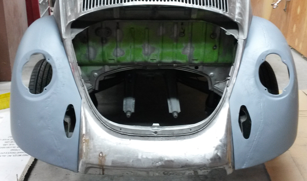
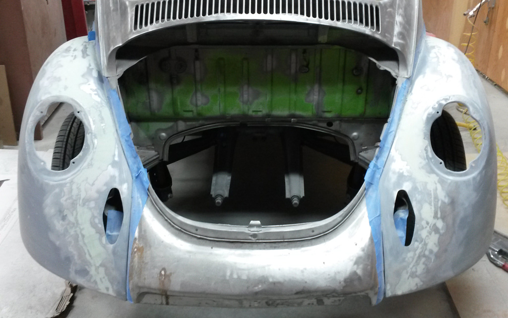
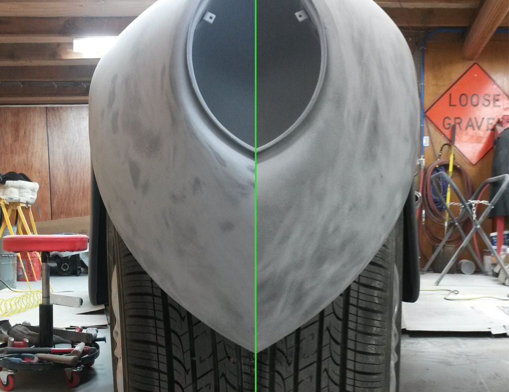
We bead-blasted the welded and ground area to make sure the 2K epoxy primer could get a good bond, then shot the outside of the fenders. The idea here is that the 2K will give the filler a good grip, and will seal any small imperfections in the welds, keeping moisture from getting under the filler:
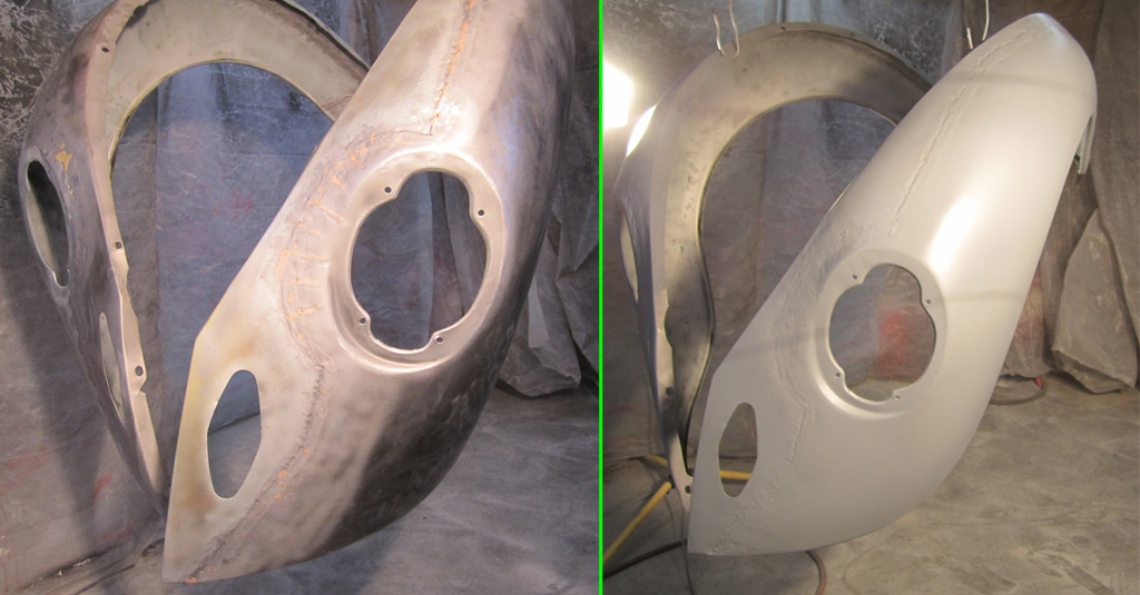
The uniform color of the 2K epoxy immedaitely makes it look better, although there is certainly evidence of the welds:
The first pass of body filler and rough sanding with 80 grit on the linear air sander shows the multiple high spots that we missed in the initial hammer work. We will tap those down and fill/sand/repeat:
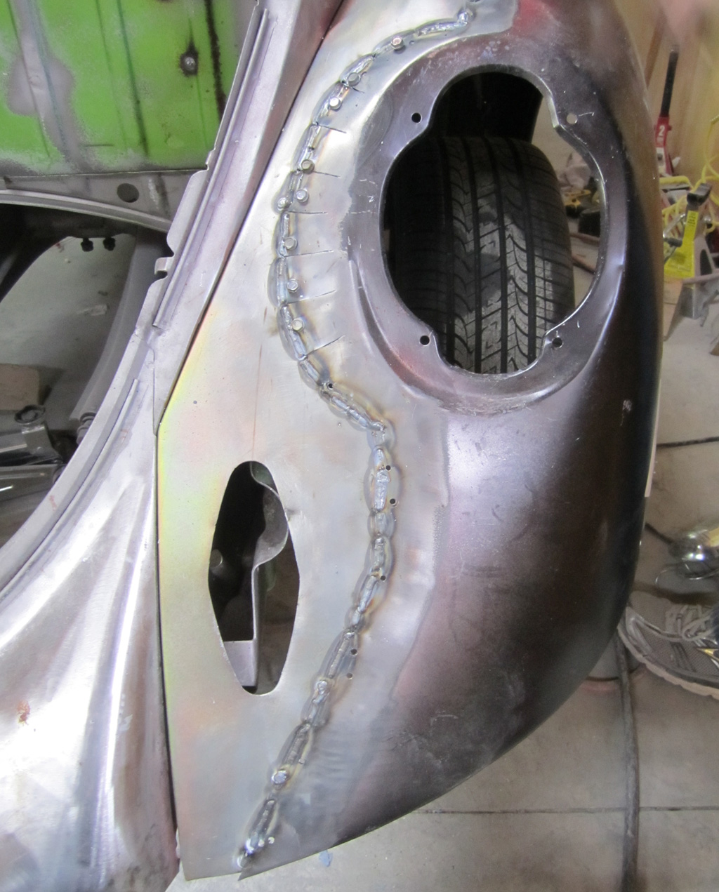
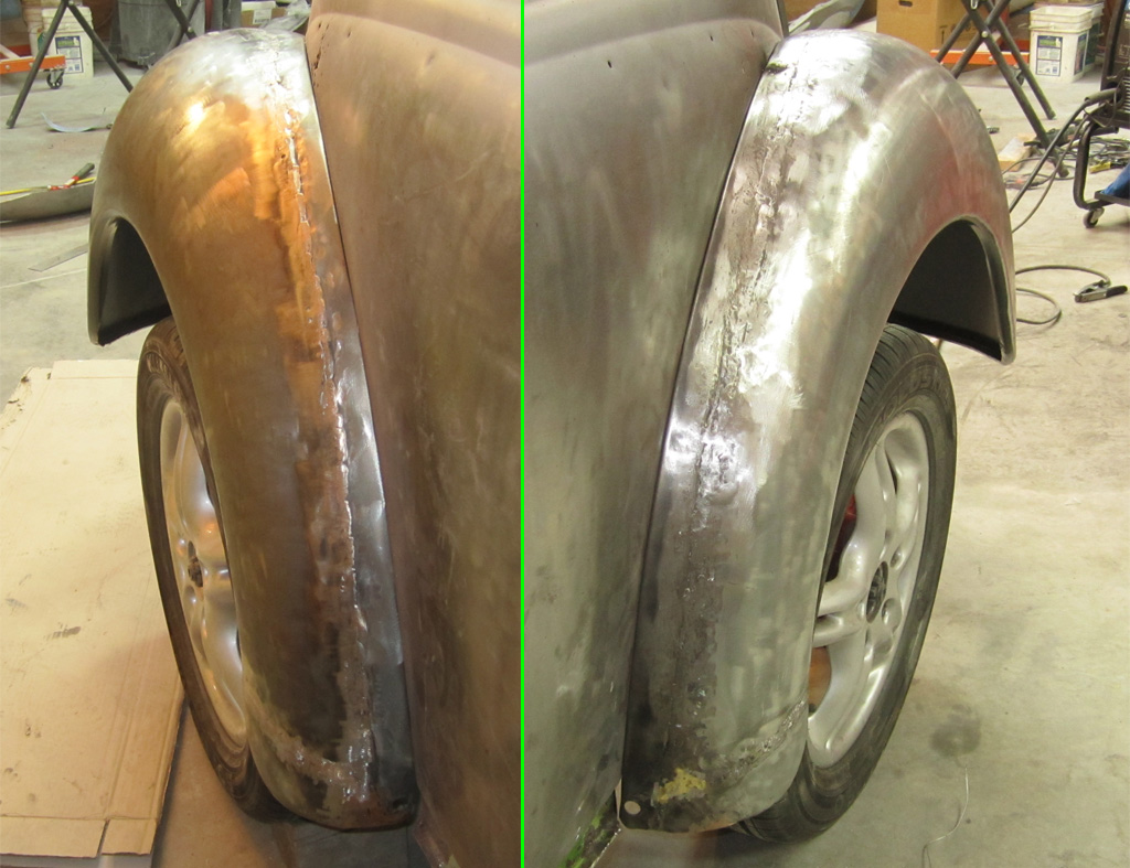
In this shot the camera is lined up carefully with the front and rear outer edges of the fender, so we can see how far the wheel is tucked under the fender. Looks about right to me:
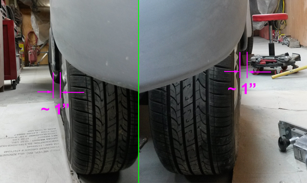
The seame kind of shot, but on the front fenders:
Last edited by Baxsie on Fri Aug 08, 2014 11:48 am; edited 1 time in total |
|
| Back to top |
|
|
Baxsie
Joined: 12 Apr 2012
Posts: 253
|
| Posted: Wed Mar 05, 2014 10:04 pm Post subject: Sofa King angry: Major Screwup on the rear fenders |
|
|
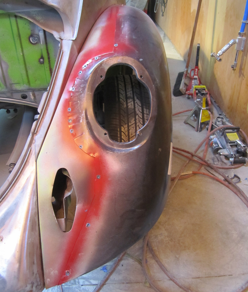
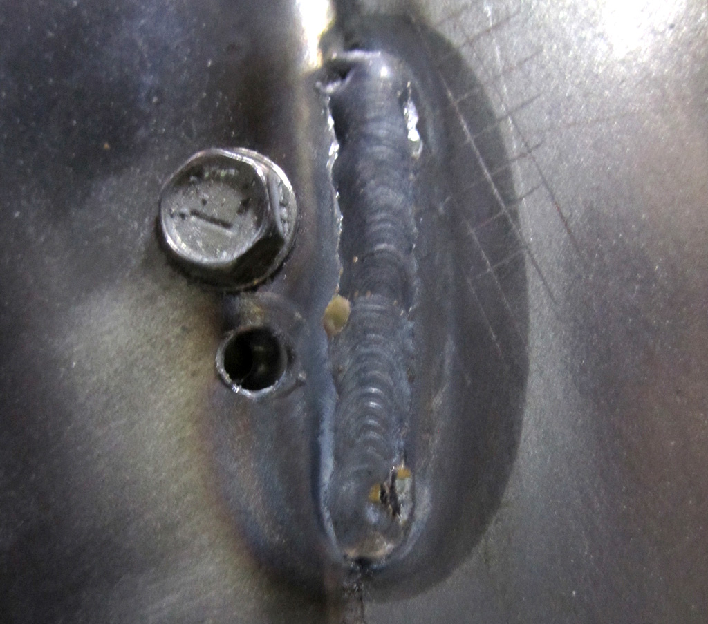
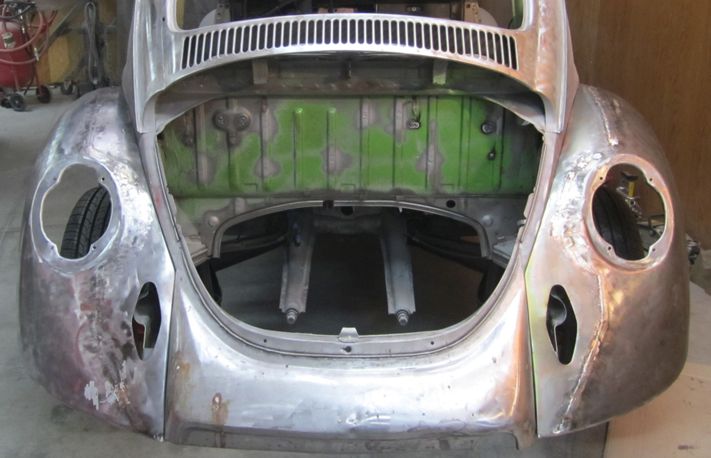
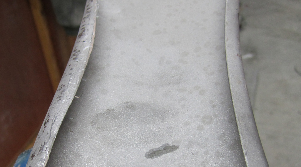
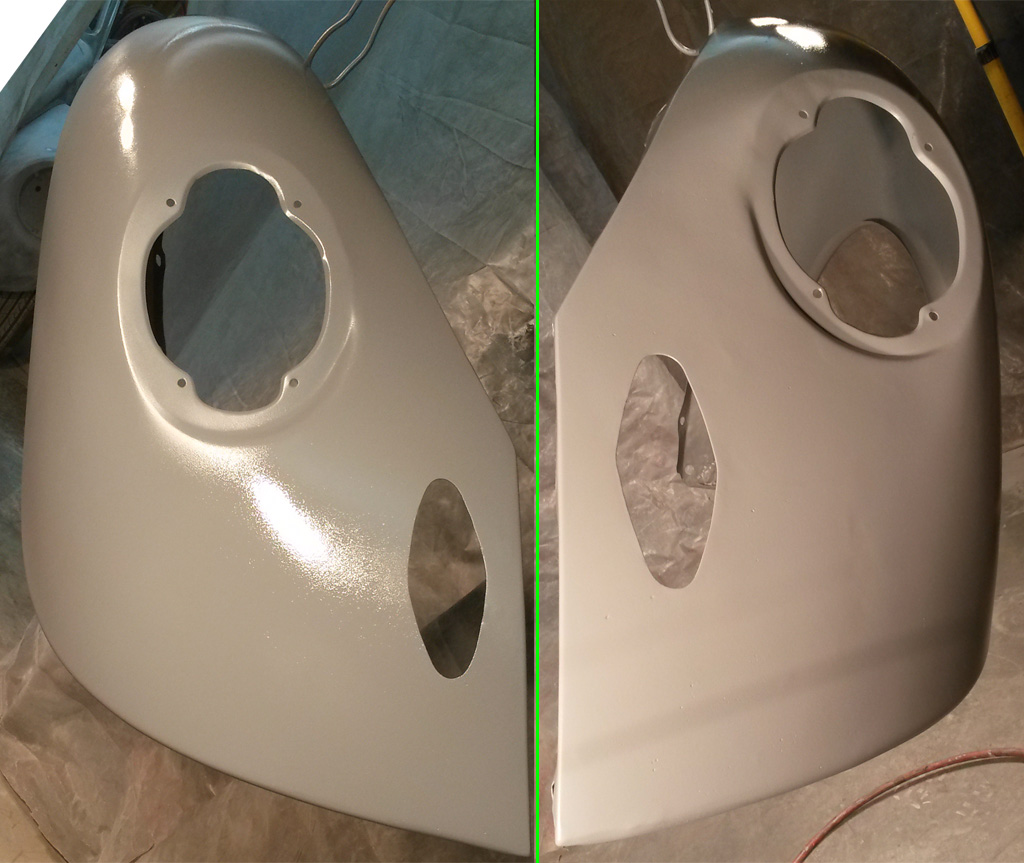
So the rear fenders were almost at the stage of putting the 2K sealing primer over the body filler. But every once in a while a little tickle would hit me when I was working around the bumper holes. See anything wrong in this picture we posted a few days ago?
I did not either, but I kept remembering this diagram from the MidAmerica catalog:

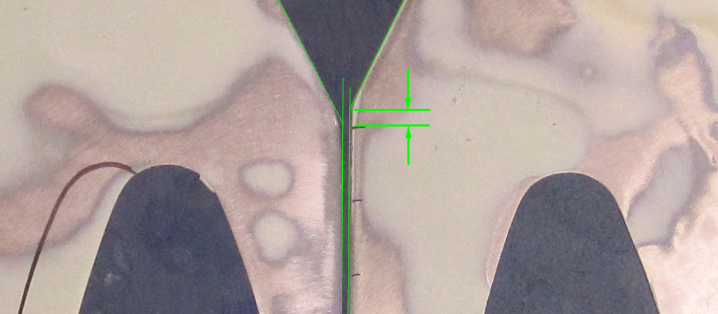
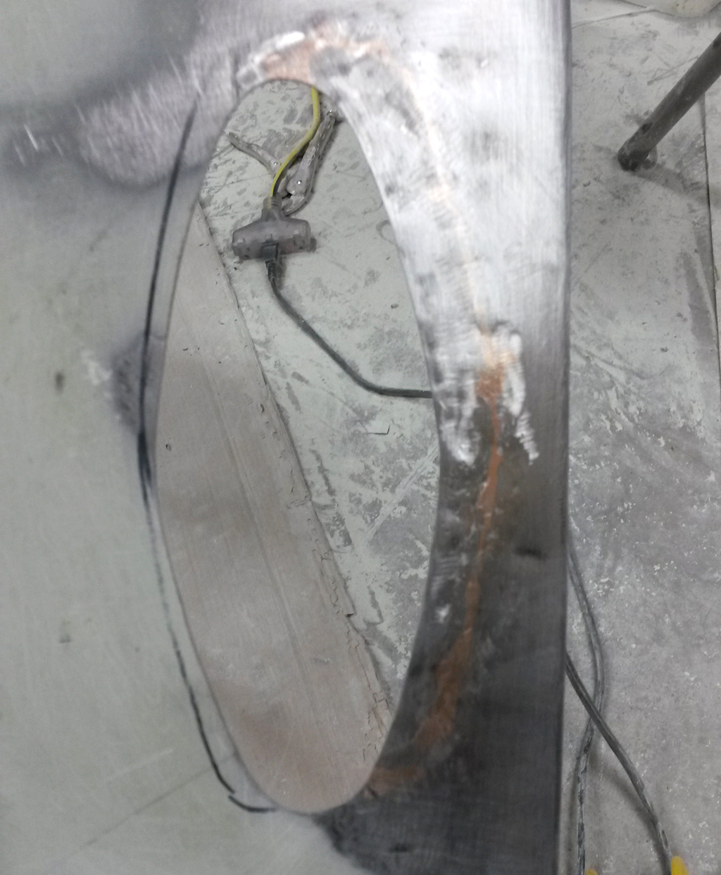
So I measured the holes on the fenders we had just widened, and were just about ready to prime:
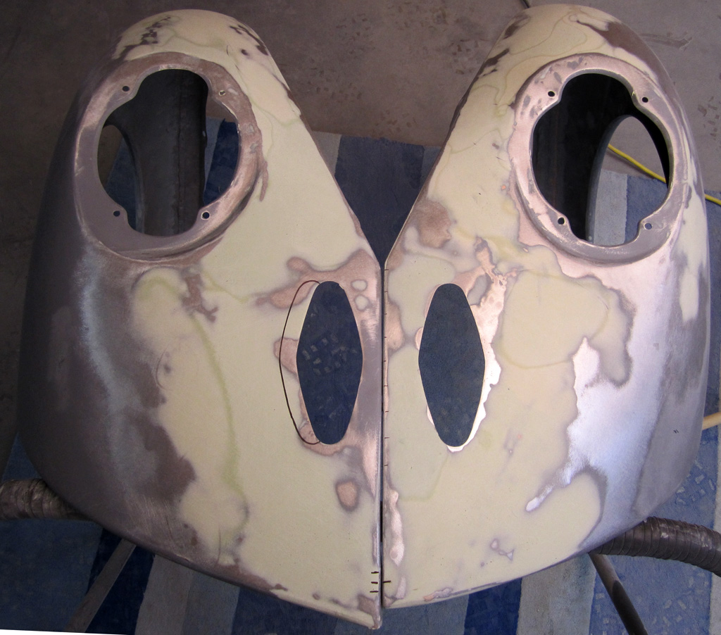
Awwww crap. I figured that I must have started with one fender from the 1975 and one from the 1974, but when I looked around the shop, only one of the four fenders old fenders had the 1.25" measurement. So the driver side rear fender on the 1975 was actually a 1974 fender. Fudge. This is where the hole should be:
Besides the hole being in a different location, the angle is in a slightly different position (yes the holes are perfectly lined up):
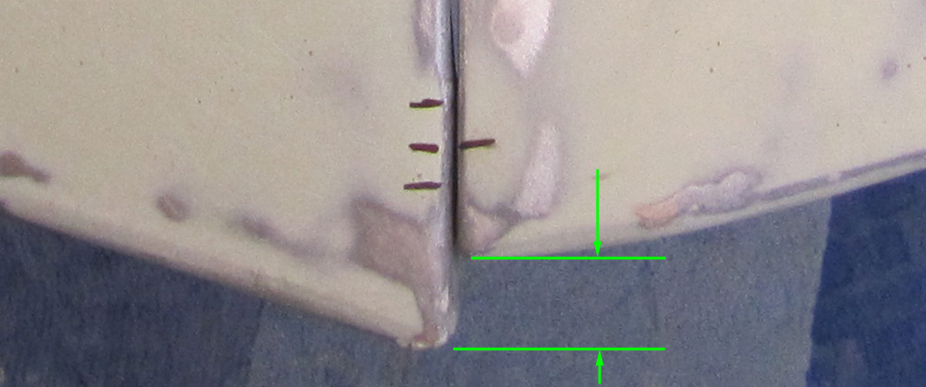
And the trailing edge is different:
Bleh. So now I gotta figure out how to fix this darn mess. I guess I'll approach it like:
1) Use the "right" fender as a template to mark the hole and bottom lip.
2) Cut one side and butt weld in a patch on the other side to move the hole.
3) Roll the bottom lip up, starting at 0" about a foot out and gently working to the full ~ 3/4"
4) Do not have a good idea on the angle thing. Bondo would crack. The piping/beading might fill it OK.
Suggestions? Mockery? Encouraging words?
Last edited by Baxsie on Fri Aug 08, 2014 11:47 am; edited 1 time in total |
|
| Back to top |
|
|
Baxsie
Joined: 12 Apr 2012
Posts: 253
|
| Posted: Thu Mar 06, 2014 8:50 pm Post subject: Creating a tool for fender beading, farm-boy style |
|
|
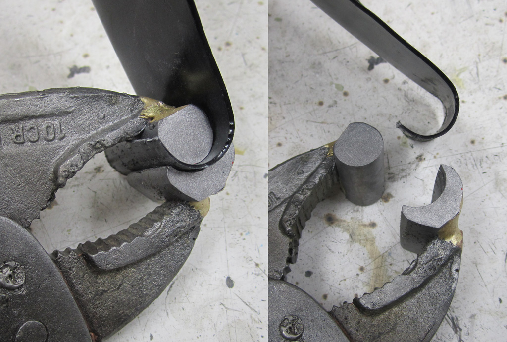
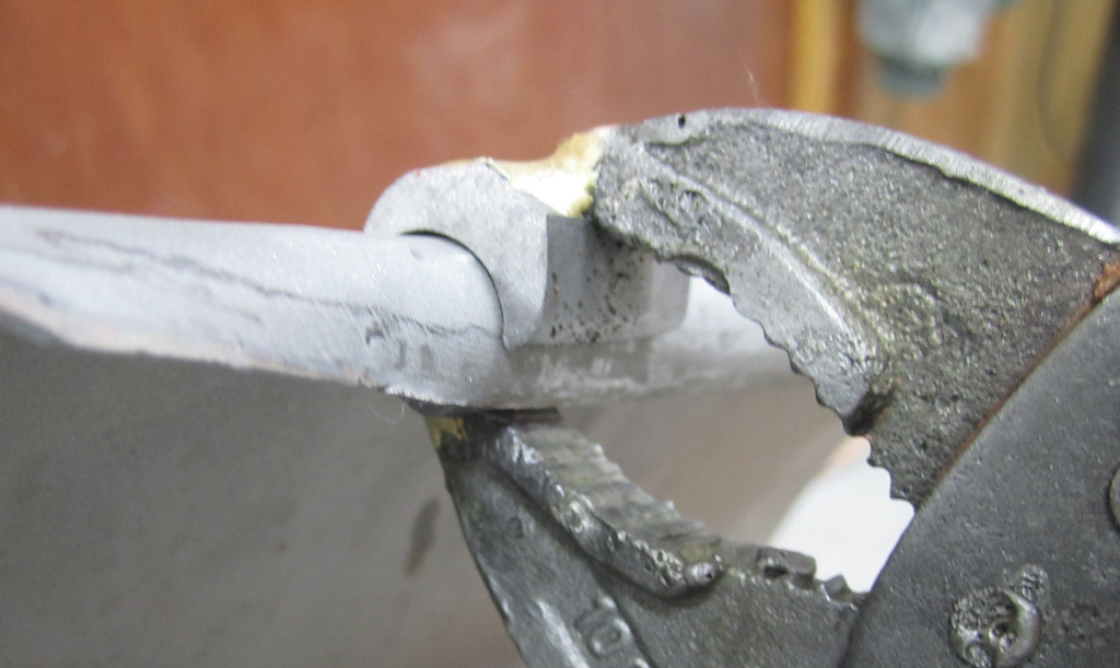
Since it looks like we are going to need to roll a new bead on the lower lip of the fender, we made up a tool. It is a chunk of 1/2" rod and a 9/16" cut-away cylinder, brazed to an old pair of vise-grips:

On a short piece of metal:
Used on a longer piece:
The new bead is on the left, factory on the right:
Last edited by Baxsie on Fri Aug 08, 2014 11:47 am; edited 1 time in total |
|
| Back to top |
|
|
Baxsie
Joined: 12 Apr 2012
Posts: 253
|
| Posted: Thu Mar 06, 2014 9:08 pm Post subject: Rear Fender conversion 1974 to 1975: Hole Patch |
|
|
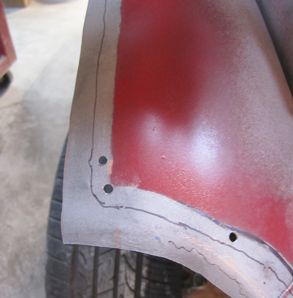
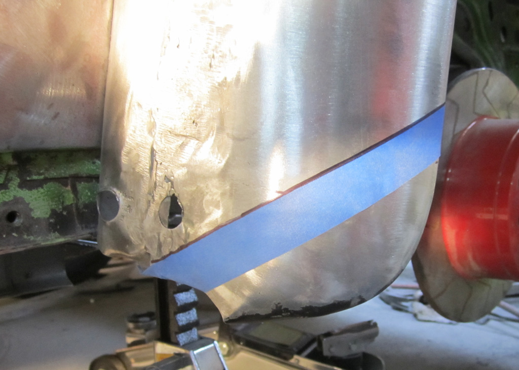
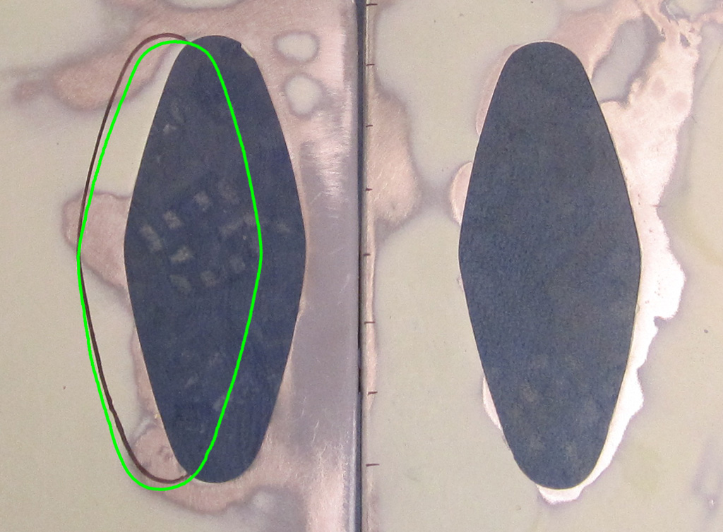
For moving the hole, we took a sliver out of the edge of the hole in one of the one of the unused fenders. It is a bit hard to see against the shadow, but it is the black bit on the right of the hole:
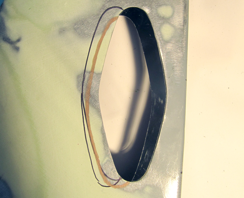
Then we will cut along the bronze line to complete the hole. Cutting does not warp, so I would much rather cut curves than weld any extra distance.
You might notice the marking is lower on the fender. To fix the gap where the angle is, we decided to push the whole fender up in the back, down in the front (rotating counter-clockwise as you look at the driver's side of the car) by about 1/8" to 1/4"so that gap where the angle is goes away. We will have to elongate the mounting holes to make that work. While looking at what this operation would require, I realized that two of the holes had been modified already. So basically whoever put the 1974 fender on had struggled with it not fitting correctly. By rotating the fender, it will make the modification of the lower fender lip a bit less.
Once these three things are done, I do not think any casual observer will be able to tell that it is not the right fender. Well, heck, it is wider, so we already know it is not "correct".
Last edited by Baxsie on Fri Aug 08, 2014 11:47 am; edited 1 time in total |
|
| Back to top |
|
|
Baxsie
Joined: 12 Apr 2012
Posts: 253
|
| Posted: Sun Mar 09, 2014 7:12 pm Post subject: Rear Fenders Wider 1975 Super Beetle |
|
|
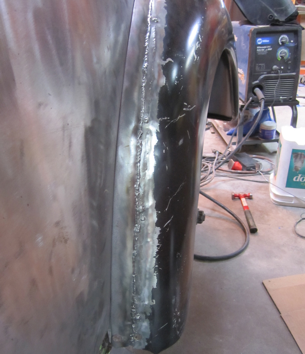
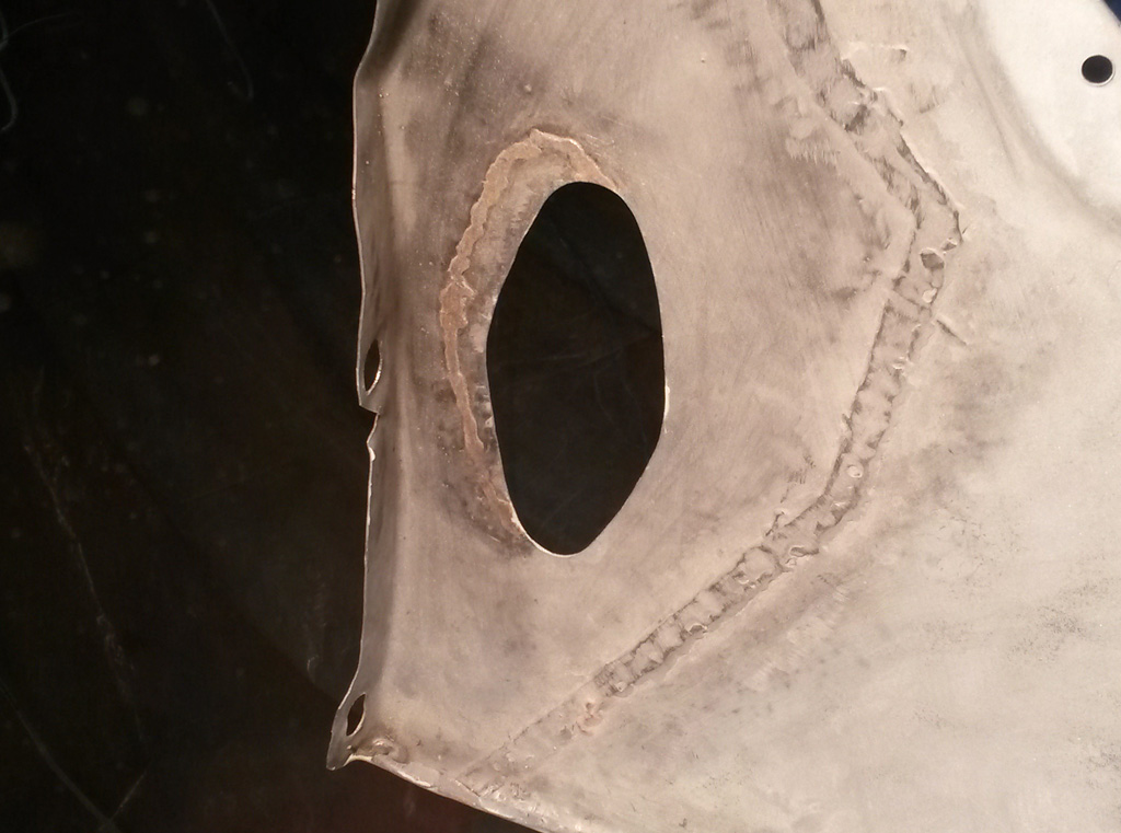
OK, looks like we have recovered from using the 1974 base for the drivers side. Here you can see the patch welded in, and hole has been moved:
The back side has a bead of the silicon-bronze left so the butt weld is a bit stronger:
Once that was done, a little fill and they were ready to have the filler sealed with 2K epoxy primer:

Last edited by Baxsie on Fri Aug 08, 2014 11:46 am; edited 1 time in total |
|
| Back to top |
|
|
Baxsie
Joined: 12 Apr 2012
Posts: 253
|
| Posted: Sun Mar 16, 2014 8:18 pm Post subject: Widening Super Beetle Fenders: Complete ! |
|
|
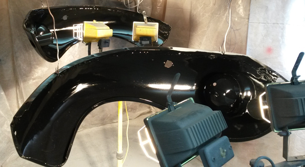
Today we declared the fender widening project complete. We had primed the underside of the front fenders with 2K epoxy, but we had missed the 7-day time window on coating over it. So we scuffed/sanded the cured 2K epoxy, re-coated with another coat of 2K epoxy, then followed it up with the gloss black. This will eventually be coated with bed liner as an undercoating to protect the fender from gravel impacts:
We have done several passes of filler/glaze/primer followed by blocking, blocking, blocking at each stage. The fenders are now primed with a coat of FEATHER FILL® G2™ Premium Polyester Primer Surfacer
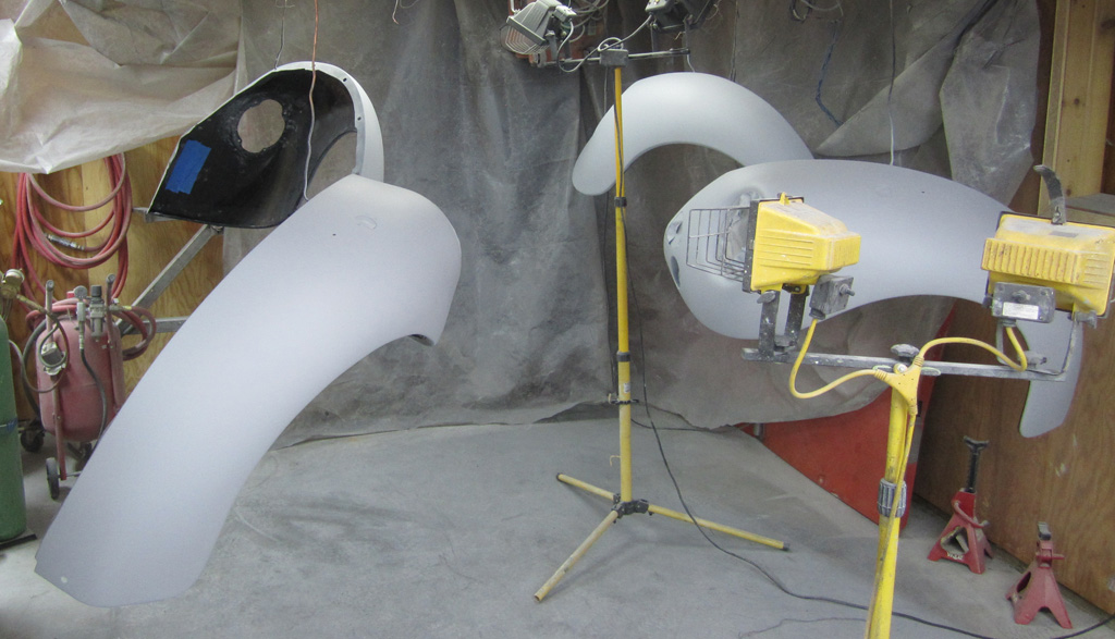
The painter will be responsible for final blocking as part of the final finish. In the meantime, this primer will protect the fenders.
Last edited by Baxsie on Fri Aug 08, 2014 11:46 am; edited 1 time in total |
|
| Back to top |
|
|
Baxsie
Joined: 12 Apr 2012
Posts: 253
|
| Posted: Sun Mar 16, 2014 8:40 pm Post subject: Test Fit of Engine, and A1 Exhaust |
|
|
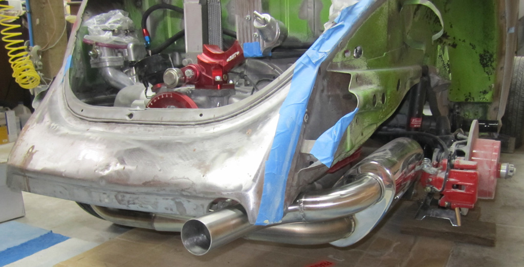
We put the engine in:
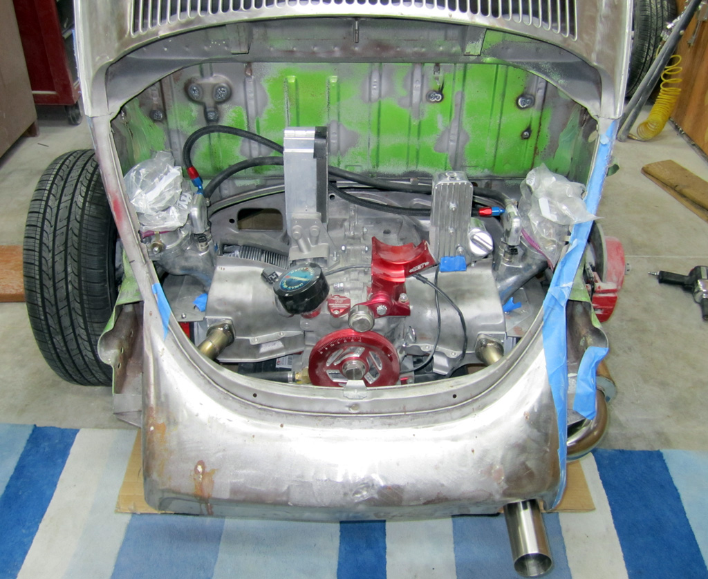
The beefy stainless exhaust pipe exits the original opening in the body:
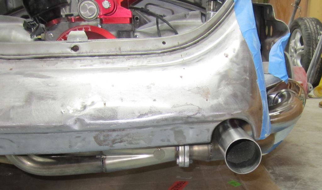
The polished muffler is tucked over in the fender area. We will need to clear the body a bit where the pipe crosses back into the engine compartment:
I am not sure how much clearance I need between the exhaust and the body. I'm sure that the exhaust pipe is larger than the original, but the opening in the body is the original size. I guess I could roll the opening out a bit.
I am also not sure how long to make the exhaust extend beyond the bodywork. I think it looks OK as it is. Easy to make it shorter.
Last edited by Baxsie on Fri Aug 08, 2014 11:45 am; edited 1 time in total |
|
| Back to top |
|
|
Bad Bug Two

Joined: 23 Feb 2007
Posts: 94
Location: Spokane, WA
|
| Posted: Thu Mar 20, 2014 3:46 am Post subject: |
|
|
You guys are doing really good work. (I'm not really much of a fan of the super beetle, but this is going to be a really nice one!)
Quick comment. Since you are going EFI, what are your plans for tuning it?
_________________
Jeff Rogers
www.badbugracing.com
9.35 @ 145 |
|
| Back to top |
|
|
Baxsie
Joined: 12 Apr 2012
Posts: 253
|
| Posted: Mon Mar 24, 2014 6:02 am Post subject: |
|
|
| Bad Bug Two wrote: | | You guys are doing really good work |
Thank you for the words of encouragement.
| Bad Bug Two wrote: | | I'm not really much of a fan of the super beetle |
Don't you be dissin the fat chicks 
| Bad Bug Two wrote: | | Since you are going EFI, what are your plans for tuning it? |
There is an application you load on a laptop that communicates to the MegaSquirt:
http://tunerstudio.com/index.php/tuner-studio |
|
| Back to top |
|
|
Bad Bug Two
Joined: 23 Feb 2007
Posts: 94
Location: Spokane, WA
|
| Posted: Wed Mar 26, 2014 4:04 am Post subject: |
|
|
What I meant to say is, are you going to tune it by seat of the pants or are you going to get it on a dyno? 
_________________
Jeff Rogers
www.badbugracing.com
9.35 @ 145 |
|
| Back to top |
|
|
Baxsie
Joined: 12 Apr 2012
Posts: 253
|
| Posted: Wed Mar 26, 2014 10:30 am Post subject: |
|
|
Oh.
I'd love to get it on a dyno. Is there a dyno here in Spokane?
There was one out on Barker road, but I am not sure if they are still around.
To get it "perfect" we could take it to a Seattle area dyno and have Mario from TheDubShop meet us there for a professional tune. |
|
| Back to top |
|
|
Baxsie
Joined: 12 Apr 2012
Posts: 253
|
| Posted: Sun Mar 30, 2014 8:30 am Post subject: Clearancing the pulley tin for oil fitting and timing sensor |
|
|
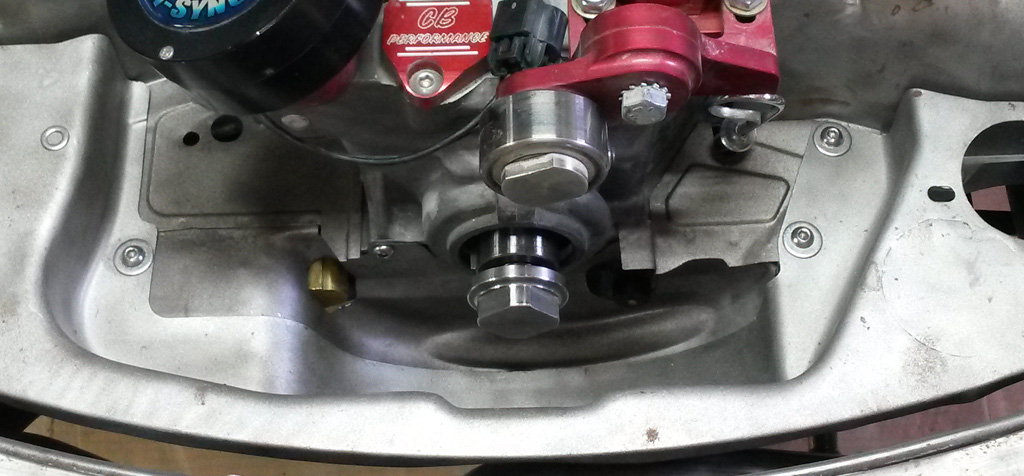
The fitting on the oil pump intersected with the front pully tin. We used a sharpie and the die grinder to make clearance:

On the other side, the VR crank sensor also needs to poke through the front pulley tin. We put a smudge on the sensor and pressed that against the tin and used a hole saw. Even so, the centering could have been better.:

Looks fine when it is all installed. We plan on painting all the tin in the Ancona blue metalic to match the exterior.:
Last edited by Baxsie on Fri Aug 08, 2014 11:45 am; edited 1 time in total |
|
| Back to top |
|
|
|
|
You cannot post new topics in this forum
You cannot reply to topics in this forum
You cannot edit your posts in this forum
You cannot delete your posts in this forum
You cannot vote in polls in this forum
You cannot attach files in this forum
You can download files in this forum
|
|